|

Pascal Casanova is a friend, passionated by the First World War, living in Verdun area. He is a very talented battlefield photograph, but also an expert in Computer Assisted Design. He lets us take advantage of his skill by designing detailed 3D rebuildings pictures of WW1 fuses and shells.
Some words from him, explaining his method to me :
The basic data (parts and functionning) are mainly coming from texts and 2D schematics of
the German
Artillery Manual of 1918.
I take note of the external dimensions of my fuses
collection, as well
as some other infos coming from the internet, mainly from your website.
The 2D schematics show the thread diameter. I use that measure to determine an
approximative value of
the drawing scale. This scale is then used to recompute the dimensions of all the other
parts.
I would like to say that I am sometimes forced to imagine the shape of some parts,
because I do not have
access to all the needed drawings. Any additional information would be welcomed to give
some potential
improvement to my works.
All the redesigned parts are then assembled one per one to rebuild the fuse. Once the
assembly is done,
I define a surface aspect that matches the fuse material, to give it a look as close as
possible to the
reality.
When the fuse is made with all its parts, it is possible to create transparent views,
cut views, or even
to realize some animated sequences.
The following pictures collection is an extract of his creations.
Percussion fuze GrZ 80 and GrZ 82

|

|
.jpg)
|
Interesting ancestors of the numerous German WW1 fuzes,
the
Gr Z 80, Gr Z 82, and Gr Z 82 (Kp) that were mounted on
projectiles of
the heavy artillery guns and howitzers (15cm and 21cm) are rendered by the magic of
the
author's 3D know-how. These pieces are rarely seen in collections or museum, so this
electronic re-enactment is the best way to observe them 'almost real'.
For
more info,
have a look to this website page dedicated to the GrZ82 fuzes.
Percussion fuse HZ14
 |
 |
 |
Family picture of the famous HZ14 series
fuses, that
was the classical devices mounted on the 10cm light field howitzers, but enough
versatile to be used with explosive shells of other intermediate caliber
explosive
shells.
From the left to the right, the HZ14 fb (an improved design with a
centifugal
safety pin), the HZ14 vorst (further design equipped with a safety pin),
and the
HZ14 vorst fliehb (last design equipped with both a safety pin and a
centrifugal
safety design).
For more details on these marks, have a look on the HZ14 fuses
webpage.
.jpg)
Percussion fuse KZ14
 |
 |
 |
Family picture of another common fuse seen on
battlefields, the KZ14 fuses series, dedicated mainly to the 7.7cm
fiekdguns.
This picture illustrates two of the marks of that fuse made in numerous
different
materials (steel, aluminum, brass), as well as a cut view showing the
security
system with compacted gunpowder grain.
More details in the KZ14 fuses
page.
Percussion fuse Gr Z 92
|
Percussion fuse Gr Z 04
 |
|
The Gr Z 04 fuse is another item
that
can be seen quite often on the former battlefields. On the right, it
is
assembled with a mighty 210 mm explosive shell.
See more
details on
the Gr Z 04
page.
|
|
Time and percussion fuze Gr Z 14
|
Another spectacular rendition showing a
common German fuze, the Gr Z 14 under a new vision : a lot of
people often forget that most fuzes were usually painted on the entire body
or partially
More details on the Gr
Z 14 fuzes
page.
Superquick percussion fuze EHZ 16
Empfindlicher Haubitz Zünder 1916 Beweglicher schlagbolzen -
Howitzer superquick percussion fuze 1916 with mobile graze
pellet
|
|
Triple effect fuze : Percussion,
superquick and delayed. It is a HZ16 fuze modification by addition
of a removable percussion rod for superquick action.
The percussion rod was not mounted before use, so that the top hole
was protected from humidity and foreign bodies introduction by a
lead plug equipped with a metallic wire loop allowing its quick
removal.
Although the fuze was useable without the percussion rod, the wire
loop is bearing a lable with the following instruction :
Draht mit platte abreissen. Steckstift einstossen, soweit
ungefärbt. Sonst Blindganger.
(Tear out the plug with the cable. Insert the percussion rod until
the painted section. Or else, misfiring.)
et de l'autre coté:
Draht mit platte erst kurz vor Schuss abreissen, da sonst
Feuchtigkeit in
zünder dringtDraht mit platte erst kurz vor Schuss abreissen, da
sonst Feuchtigkeit in
zünder dringt
(Only remove the cap before firing. Or else the humidity will enter
inside the
detonator.)
This fuse used to arm the elongated 10, 5 cm shells of the type
lg.F.H.Gr., high
explosive
or blue cross toxic.
More details on
this fuse on the EHZ
16 fuze
page.
Superquick percussion fuse EKZ 17
|
|
The EK Z 17 fuse is more
rarely encountered on the former battlefields nowadays.
Moreover, the surviving items are often heavily damaged and
corroded, and the percussion rod is often missing. More details
on the EKZ 17
fuses page.
 |
Fuze at rest, the percussion rod is blocked by the centrifugal rod pressed by a spring |
|
Fuze during the flight, the shell spin pushes the centrifugal lock away, freeing the percussion rod movements |
|
Fuze during the flight, zoom on the safety spring at the bottom of the percussion rod, preventing it from being pushed back by the wind |
|
Fuse hitting its objective, the percussion rod compresses the safety spring, and the percussion pins ignites the starter. |
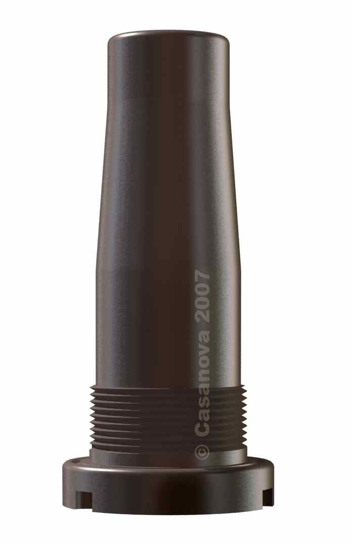
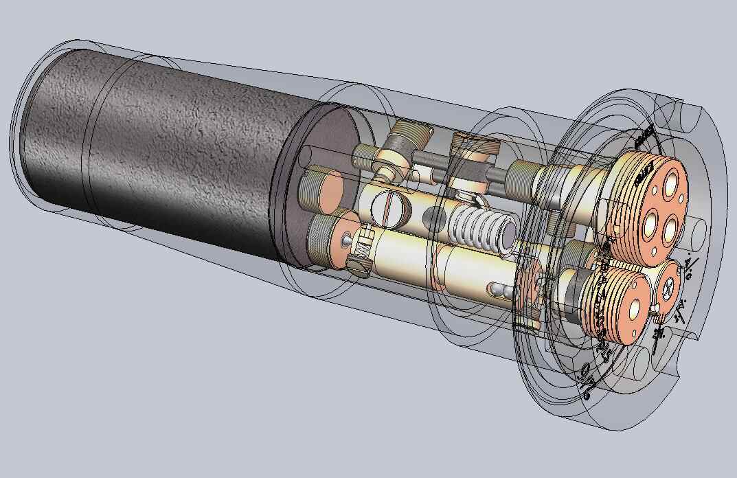
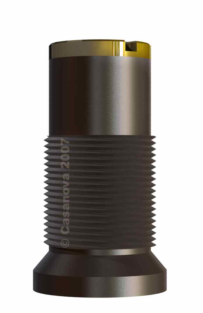
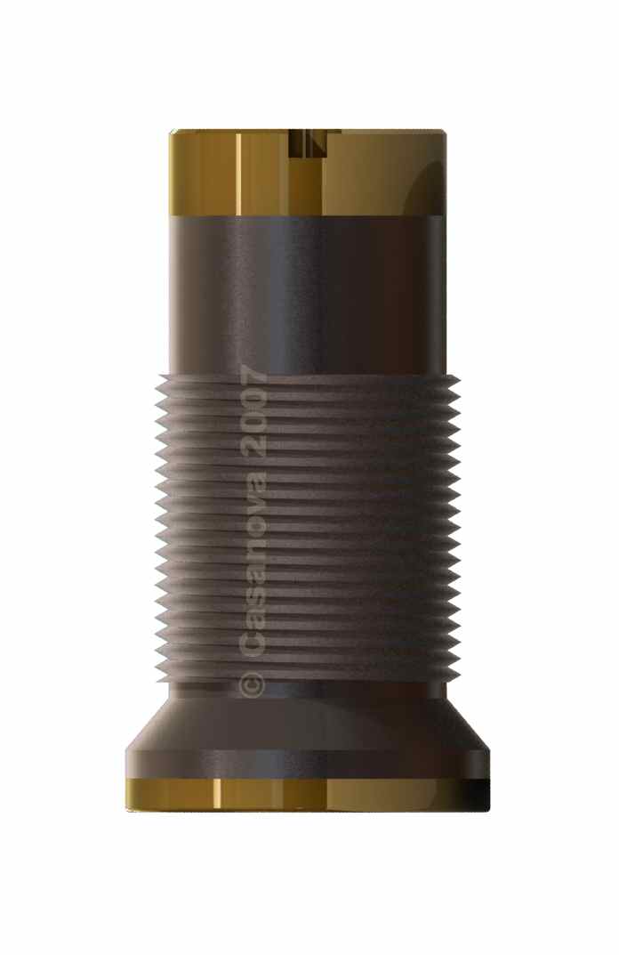
Superquick percussion fuze Gr Z 17
|
 |
The Gr Z 17 fuze
cannot be observed easily nowadays. It was assuperquick
percussion fuze dedicated mainly to the 150mm and 210mm
heavy howitzers, for high explosive or gaz shells.
Its inertia arming system and its percussion rod
system is brilliantly shown in this impressive
picture.
aufschlagzünder mV (fuze for anti-tank shell)
 |
 |
This aufschlagzünder mV
equipped the 7,7 cm. K. Gr. 15. m. P shells for anti-tank
use, under a steel hat.
 |
|
Time and percussion fuse Dopp Z 86
|
|
The Dopp Z 86 is
the ancestor of most of the German time and
percussion fuses found during WW1. Pascal Casanova
not only recreated 3D views of that old fuze, but he
also wrote a interesting article on it in the Nr 6
edition of 'Tranchées Magazine' (jul-aug-sept
2011)
Time and percussion fuse Dopp Z 92

|
|
The Dopp Z
92 fuse is relatively often found
nowadays on the former battlefields, most of the
time still assembled with the ton part of a
schrapnell shell. But it never shines like this
one ! More details on the Dopp
Z 92 fuse page.
Time and percussion fuze HZ05
|
|

|
The HZ05
fuze can be found easily in the WW1
battlefields in all of its variants, but
most of the time in badly corroded condition
since its time rings were made in aluminium.
This virtual view let us imagine its aspect.
More details on these fuzes on this website
page HZ05
Gr fuzes and
HZ05 Schr fuzes.
Fusée à Double effet KZ 11 and KZ 11 Gr
 |
|
 |
|
Time and percussion fuze LKZ 11
|
|
The
elogated time and percussion LKZ
11 fuse is for me one of the
most beautiful ones of the German
arsenal of WW1. This reconstitution
is just convincing me a little more
in my feeling. More details on this
fuze on the page fuze
LKZ 11 Gr.
Time and percussion fuze Dopp Z S 43
|
|
This 30mm time and percussion
fuze Dopp Z S 43 ,
graduated from 0 to 43 seconds
is pretty rare, and was
principally used with German
Navy guns (such as the famous
15cm SKL 40), or coast guns.
This reconstitution is therefore
even more precious.
Bottom fuse Bd Z 10 (Lg Bd Z 10 and Kz Bd Z 10)
|
|
|
The bottom fuse Bd Z
10, preferred
German fuse for the 150,
210 and 280 mm calibers,
existed in two main
marks, screwed either on
a short detonator, with
25 grammes of picric
acid, or on a long one,
with 100 grammes of
picric acid. It was then
respectively named Kz
Bd Z 10 or Lg
Bd Z 10. For
more details please go
to the Bd
Z 10 fuse
page.
Bottom fuse Spgr.m.K and m.V.u.K.
|
|
The bottom fuse
Bd Z f Spgr
m.K.
equipped the shells
of the famous long
range 380 mm heavy
guns, as well as the
280, 240, and some
210 mm shells. There
was a mark with a
short delay, named
Bd Z f Spgr
m.V.u.K..

|
Fuse at rest, the centrifugal locks are blocked by the locking rod |
|
Fuse at the shot departure, the locking rod is pushed ahead by the pressure of the combustion gases on a rear membrane |
|
Fuse during the flight, the centifugal locks are pushed away |
|
Fuse hitting its objective, the percussion pin hits the starter. |
Fuze for light Minenwerfer IWMZdr2
|
|
|
The
l.W.M.Zdr
and Zdr2
fuzes are
used on
light trench
bombs
(leichte
Sprengmine),
filled with
high
explosive or
gaz.
The Zdr2
differs from
the Zdr by
the presence
of a two
rods safety
pin, and a
gaine
screwed on
the fuze
tail
equipped
with a
detonator.
These fuzes
head has a
top socket
allowing the
introduction
of a special
key in order
to extract
the bomb
from the
tube in the
case of a
misfire.
This socket
is also used
for the
fixing of a
light-hiding
cap for the
models not
equipped
with a top
head
screw.
More details
on the lWMZdr
and lWMZdr2
fuzes
page.
Aufschlagzünder 1916 für leichte Wurfmine (Percussion fuze model 1916 for light trench mortar bomb)
|
|
This
fuze is
designed
for the
bombs of
the 7,6
cm trenc
mortar,
high
explosive
or gaz
filled.
The bad
inflight
stability
of these
projectiles
induced
the need
for the
development
of this
fuze
equipped
with a
percussion
system
that
will
operate
whenever
the
shell
falls on
its
head,
base or
any
other
direction
at
impact.
The fuze
head is
made of
zinc.
The
exploder
contains
an
approximate
17 gr
picric
acid
charge.
Fuze for heavy Minenwerfer Z.s.W.M. 13
|
|
Fuze for heavy and middle Minenwerfer Z.s.u.m.W.M.
|
|
Booby trap very long delay Lgz Z 17 fuz
|
|
|
|
|