|
fuzes designed for high explosive shells had to be equipped with a powerful exploder (or 'gaine' - in German 'Zündladung'). Thes gaine were often screwed on the tail of the German fuzes, rather than mounted into the shell like for French ones. This characteristic is making those pieces very dangerous still nowadays, when the exploder is still present. The shells whose explosive did not need any exploder had to be equipped with specific fuzes.
German military engineers preferred to design specialised fuzes rather than a small number of models with options. Therefore, there is larger amount of different types and marks compared to the little number of English types or the limited one of French fuzes.
the will to offer to the batteries multifunctional fuzes able to operate with different selectionable effects (percussion, delayed, super_quick, time, ...) or wityh different kinds of shells induced the development of devices whose complexity became in some cases extreme.
the lack of metals caused by the blocus of Germany soon induced the replacement of bronze or brass with aluminium or zinc alloys, or steel. Since those materials have lesser resistance to corrosion, those types of German fuzes that you can observe nowadays on the former battlefields are sometimes in a bad condition.
The markings are complex and most of the time stamped into the fuze body. They generally indicate with abbreviations the working principles or planned use of the fuze :
This codification is generally accompanied by two digits indicating the fuze design or revision year, and sometimes specific informations on the shell type to be used with the fuze, internal options, etc....
The markings also give very often informations on the manufacturing of the given specimen, such as the name of the arsenal or plant that produced it, the year of production, control or lot numbers, etc... For additional info, see the specific section of this websiten dedicated to the 'German fuzes manufacture markings'
Gr Z c/80, c/82 and c/82 Kp fuze |
||
 |
The Gr Z c/80 percussion fuze was a stepstone in the German percussion fuzes story, whose previous arming mechanisms were up to then made of heavy transversal safety pins ejected by the centrifugal force when the shell was leaving the gun, just as in the percussion fuze M 1873. However, it kept the usual German graze action percussion system (percussion pin graze pellet and static starter).
This Gr Z c/80 fuze was organized on a principle somehow comparable to the French 'Budin Mle 1875 fuze'. Like in the French fuze, the safety of the Gr Z c/80 fuze at rest was insured by the position of the top of the percussion pin hidden inside of an internal mobile graze pellet, that was armed at the discharge. It must be noted that no safety spring was preventing the percussion pin from hitting the primer once armed, during the flight. In a later model, named Gr Z c/82 fuze, an additional safety device was integrated, the top head descending into the fuze head by momentum action at the shot of discharge, therefore only bringing the primer in a position that could be hit by the graze pellet percussion pin. This fuze was designed for high explosive ('Gr' = Granate - explosive shell) and incendiary heavy calibre shells of the :
A variant named Gr Z c/82 (Kp) was equipped with a safety spring and a different inertia block. Externally, it was only distinguishable by the presence of a steel cap covering the fuze head. These fuzes percussion systems were also used for the first German time and percussion fuzes Dopp Z c/85 whose percussion and concussion removable mechanism named DoppZdSchr c/85 ('DoppelzünderSchraube') was inserted into the time system (revolving discs) just before the shell firing. |
|
GrZ c/82 and GrZ c/80 fuzes. The additional safety ring that makes the main difference between both models is visible |
||
 |
 |
|
GrZ c/82 and GrZ c/80 fuzes. Another difference, just cosmetic, can be seen in the macining of the top plug surface |
GrZ c/82 and GrZ c/80 fuzes. Rear view on the flame communication channel. |
|
 |
 |
|
GrZ c/80 fuze. Lateral view. Picture courtesy Luc Malchair |
GrZ c/82 fuze. Lateral view. |
|
 |
||
fuze GrZ c/82. Wartime scheme |
||
Return at the top of the page |
||
Gr Z 92 fuze |
||
 |
Entirely made of brass, purely percussion-type and without delay, this fuze replicated almost indentically the arming and percussion systems of the same generation 'Dopp Z 92' time and percussion fuze, and that will be used in all the German time and percussion fuzes until 1905.
Just as this latter, the Gr Z 92 percussion fuze was secured with a two rods safety pin, to be removed before the shot. This liberated the movements of the graze arming system, whose massive mobile graze pellet (bearing a primer) slided back under the discharge momentum action and hit a fixed percussion pin protected at rest by a tulip spring cap having the shape of a crown and flattened under the pellet pressure, setting fire to a big gunpowder pellet. This pellet combustion made possible the movements of the main percussion system graze pellet located in the fuze tail. At impact, the primer-bearer cylinder was propelled against a percussion pin fixed onto a transverse bridge. The resulting flame was directed backwards through the fuze tail base hole, and bursted the gaine exploder. This fuze was designed for the high explosive ('Gr' = Granate - Obus explosif) or gaz heavy shells of the
|
|
fuze GrZ 92. Nice specimen observed in the Somme. Markings are still well visible : (Gr Z 92 - RM 16 - 140) |
||
 |
 |
|
fuze GrZ 92. Rear view - indication 'B' |
fuze GrZ 92. Front view. |
|
 |
 |
|
fuze GrZ 92. Detail showing the escape hole for the gasses created by the burning of the security gunpowder grain, ignited at the departure. This hole is still closed by the original thin brass sheet. |
fuze GrZ 92. Detail of a lateral opening, of unknowned function |
|
 |
 |
|
fuze GrZ 92. Mounted on a threaded adaptor. Makings 'Gr Z 92 - Kr 17 - 7'. 'Kr' meaning 'Krupp'. |
fuze GrZ 92. The head cap has disappeared, giving a view on the percussion pin pellet of the security system. On the side, view on the two safety pin holes, and opened gaz escape hole |
|
 |
 |
|
fuze GrZ 92. Another one, markings 'Gr Z 92 - (lion) 17 - 73'. Thie identuty of the manufacturer associated with that animal symbol is unknown |
fuze GrZ 92. Another specimen. Markings 'Gr Z 92 - AEG 17 - 19'. Picture courtesy Luc Malchair. |
|
 |
||
fuze GrZ 92. Wartime scheme |
||
Return at the top of the page |
||
Gr Z 96/04 fuze |
||
 |
Brass fuze derivated from an older Gr Z 96, with a steel mantle and attached exploder steel exploder.
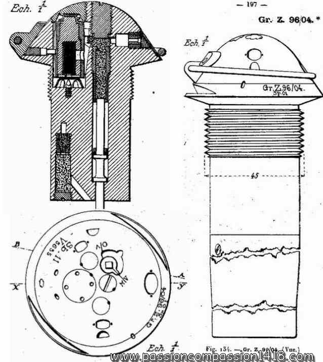
The Gr Z 96/04 fuze was a percussion graze fuze with optionnal delay, built around two parallel graze action percussion systems located in the tail. These two apparatus were practically identical, designed on a cylindrical graze pellet bearing a starter and a static percussion pin transverse bridge, but for the presence of a compressed gunpowder acting as a delay in the flame communication channel from the delayed percussion system to the detonator. The behaviour was selectable by the rotation of a setting stud commanding a vertical inner rod that deviated the flame to the adequate system. Depending on the selection it was positioned on 'oV' position (Ohne Verzögerung - without delay - let both systems activated) or on 'mV' position (mit Verzögerung - with delay - deactivating the undelayed percussion system). The arming system was secured at rest by a two rods safety pin. It was based on a the 'Dopp Z 92' fuze design : an axial and massive mobile graze pellet bearing a starter, a percussion pin protected by a tulip spring cap, and compressed gunpowder pellet blocking the percussion system. In this specifice model, the graze action arming system commanded the combustion of two compressed gunpowder pellets, one for each percussion system, that liberated the movements of two stems blocking the two mobile pellets. Another interesting characteristic of this fuze was its additional safety system for the exploder, inherited from the older type fuze Gr Z 96. At rest, its primer was placed within an isolated detonation room in wich it could explode without communicating the energy to the surronding relay-charge. At firing time, the combustion of a compressed black powder grain was freeing its movements inside a brass tube so that the landing shock inertia could push it just in front of a windows communicating with the explosive load. That fuze was used with the high explosive shells ('Gr' = Granate - Explosive shell) of the :
|
|
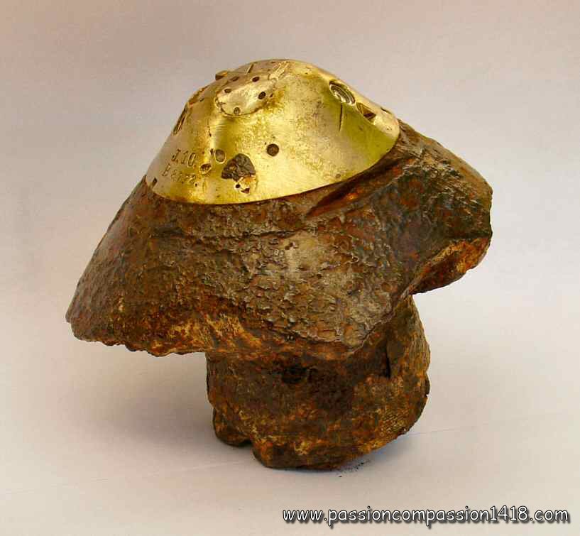
GrZ 96/04 fuze. Characteristic shape, with its top in one single brass mass. Markings 'J 10 - B 4720'. |
||
 |
 |
|
Side view of fuze GrZ 96/04 with parts of the tail still attached. Markings 'Sb 09 - D 9???' : manufactured in Strasburg in 1909 |
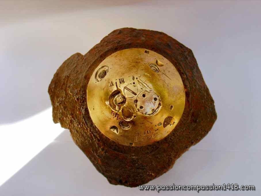
Top view of fuze GrZ 96/04 observed in Champagne. Markings 'Sb 10 - O 8979', manufactured in Strasburg in 1910. |
|
 |
 |
|
fuze GrZ 96/04. Still attached to a fragment of the shell head, evidently a large caliber one. The thickness of the steel wall of the shell (over 25 mm) makes us think to a 210 mm shell ! The shell remains keep some traces of red-brown painting |
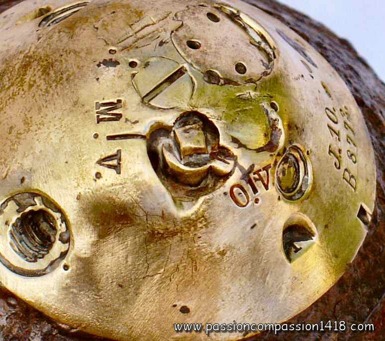
fuze GrZ 96/04. Top view, with lever for selection of the delay, caps for the two percussions systems (with and without delay) and for the arming system with stem and powder grain. Markings : J.10 - B8772. The letter 'J' means 'manufacturerd in Ingolstadt arsenal' |
|
 |
 |
|
fuze GrZ 96/04. Detail of the delay selection lever 'm.V./o.V.' : this fuze have been shot with the position 'o.V.' (without delay)'. See the red paint traces in the engravings |
fuze GrZ 96/04. Wartime scheme |
|
 |
||
fuze GrZ 96/04. Lateral view on the exploder safety system brass tube that led to the detonation room (disappeared). |
||
 |
 |
|
Fuze GrZ 96/04. View on the exploder safety system brass tube, cut at the level of the communication windows. |
||
 |
||
Older fuze GrZ 96. Wartime scheme with the exploder safety (detonation room) that was also existing on the Gr Z 96/04. |
Fuze GrZ 96/04. Bottom view |
|
Return at the top of the page |
||
Gr Z 04 and Gr Z 04/14 fuze |
||
 |
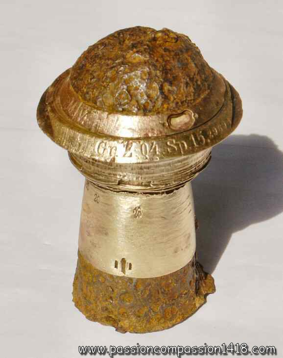
Brass or zinc alloy fuze, with steel cap and gaine. The GR Z 04 was an evolution of the Gr Z 96/04 fuze, including as this latter :
The Gr Z 04 fuze was intensively used. It was mounted on the high explosive shells, false head high explosive shells, smoke and gaz shells of the :
There are two known variants :
|
|
fuze Gr Z 04. Markings 'Gr Z 04 Sp15' |
||
 |
 |
|
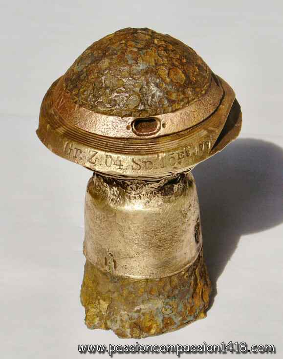
fuze Gr Z 04. Nice specimen with marking 'Gr Z 04 Sp15 - z9694 - O/V - M/V - ZE - 45 - 12 - 83 - 20 - 28 - C - ABC - 82' |
fuze Gr Z 04. Another specimen with markings 'Gr Z 04 Sp15 - E3177 - O/V - M/V - 48 - 18 - 99 - 17 - B70 - 81'. Note the narrowed section at the threading level, caused by the pressure of the explosion. |
|
 |
 |
|
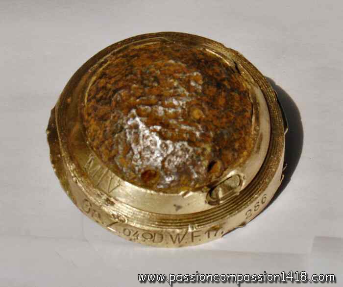
fuze Gr Z 04. Another piece, only the top is remaining, with markings 'Gr Z 04 - O - D.W.F. 17 - 286 - O/V - M/V'. |
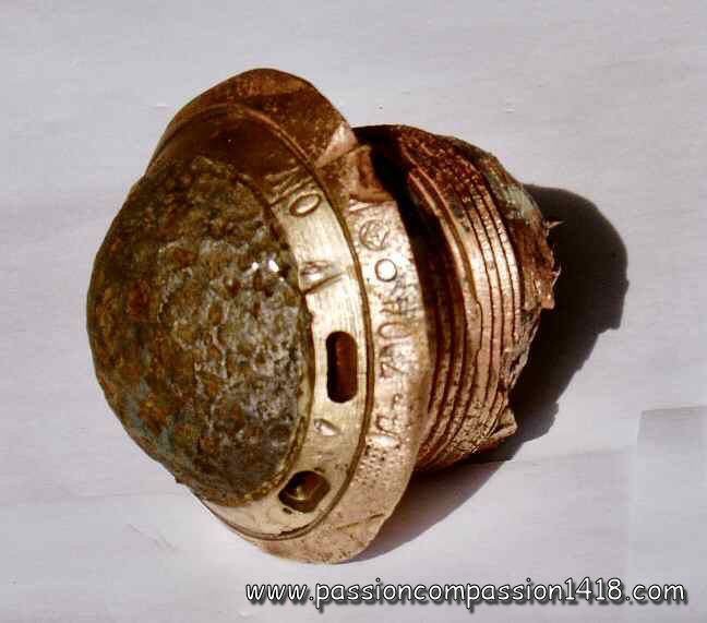
fuze Gr Z 04. Another damaged piece, with markings 'Gr Z 04 - O - square in a circle - 17 - 141 - O/V - M/V' |
|
 |
||
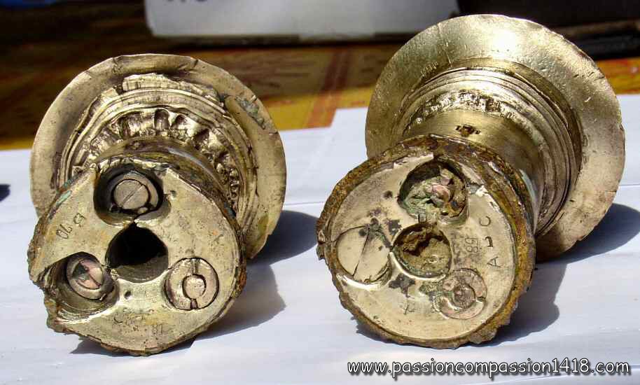
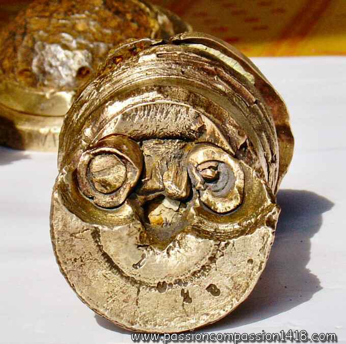
fuze Gr Z 04. View from below showing the exits of both the percussion systems, the end of the stem of the arming system, and the one of the detonator |
||
 |
 |
|
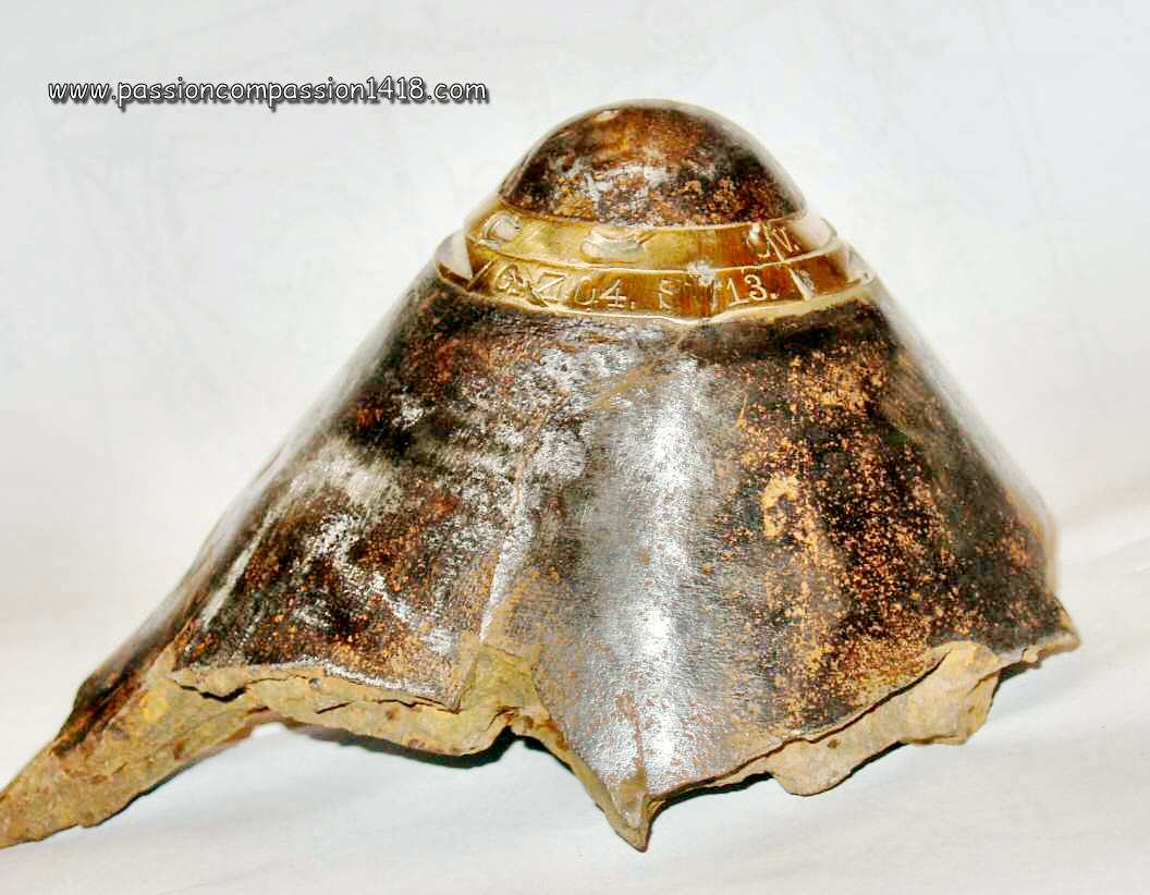
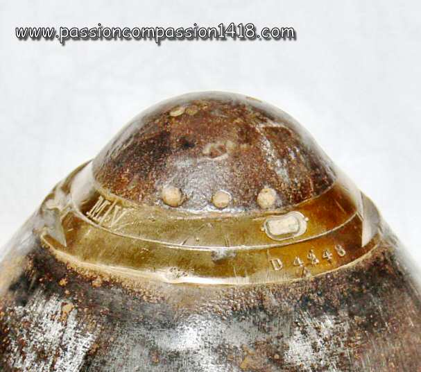
fuze Gr Z 04. This one is still in place on top of a 210 mm shell head (marked 'GFSb'); markings 'Gr Z 04 S? 13 - D 4248 - O/V - M/V |
fuze Gr Z 04 mounted on a 210 mm shell head. Zoom showing the holes for the safety pin. |
|
 |
 |
|
fuze Gr Z 04/14. All markings have disappeared on this specimen, but it is clearly a mod14 model, since no detonator security stem is visible on the bottom (compare with the pictures above) |
fuze Gr Z 04. Wartime scheme |
|
 |
 |
|
fuze Gr Z 04. Top view on the safety pin. Markings 'Gr Z 04 Sp15 - J2985' |
||
 |
||
fuze Gr Z 04. Complete specimen with its impressive 90g picric acid primer (relay charge) |
fuze Gr Z 04. Bottom view |
|
 |
||
fuze Gr Z 04. Dismantled top showing the revolving discs organization. |
||
Return at the top of the page |
||
Gr Z 14 and Gr Z 14 n/A. fuze |
||
 |
Despite its shape close to the Gr Z 04 fuze one, and therefore often confused with it, the Gr Z 14 fuze is a device with a totally different inner organization.
This fuze is in fact the percussion model designed for the heavy artillery high explosive shells, derivated from the new generation of 1914 German fuzes with a technology initially developped for the 'KZ 11' fuze, but also integratezd into the 'KZ 14' fuze for the field guns, and into the 'HZ 14' fuze for the field howitzers. The Gr Z 14 was made in brass with a steel cap and gaine, and had a 45 mm thread. Like the other fuzes from the same generation, it was based on a two components graze arming system (mobile graze pellet with starter, and gunpowder pellet stopping a safety stem that blocks the main percussion system), and a main graze percussion system (mobile graze pellet bearing the starter and static percussion pin, with safety spring and blocked by a safety stem). If the inner organization was totally different, it was functionnally only a simplification of the Gr Z 04 fuze, being a heavy caliber shell percussion fuze with no optional delay nor exploder safety system. It was equipped with single rod safety pin for the graze arming system. This fuze was used with numerous projectiles during the war. It was mounted on the high explosive shells, incendiary shells and gaz shells (green, yellow and blue cross) of the :
Some variants :
|
|
Kz Gr Z 14 fuze |
||
 |
 |
|
Fuze Gr Z 14 n/A. Mounted on an approximative 110 mm calibre shell head. Observed in Verdun. |
Fuze Gr Z 14. specimen in bad condition, markings 'Gr Z 14 - DWE 15' |
|
 |
 |
|
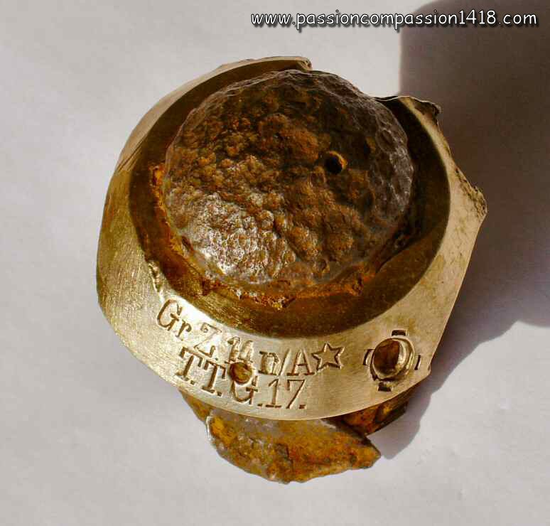
fuze Gr Z 14 n/A. Another piece badly damaged, but with clearly visible markings : 'Gr Z 14 n/A (star) - T.T.G.17' |
fuze Gr Z 14 n/A. Almost unreadable markings 'Gr Z 14 n/A * (star) - DT 17' |
|
 |
 |
|
fuze Gr Z 14. Another one, markings : 'Kz Gr Z 14 -22 - ll - 15 |
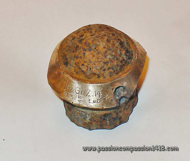
fuze Gr Z 14. Again another one, markings 'Kz Gr Z 14 (star) - N15 - 85 - E.u.Co' |
|
 |
 |
|
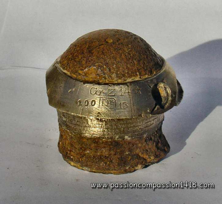
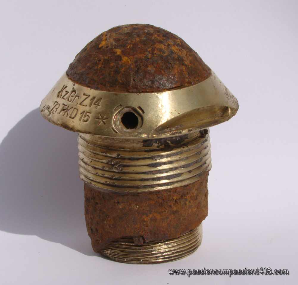
fuze Kz Gr Z 14. This one observed in Champagne is in pretty good condition; Markings : 'Kz Gr Z 14 - 73 TKD 15 (star)' |
fuze Kz Gr Z 14. Bottom view of the same specimen. |
|
 |
 |
|
fuze Gr Z 14. View from below showing the flame hole to the exploder |
fuze Gr Z 14 n/A. Wartime scheme |
|
Return at the top of the page |
||
KZ 14, KZ 14 Fb, KZ 14 Vorst, KZ 14 mV, and KZ 14 n/A. fuze |
||
 |
The sophisticated 'KZ 11' fuze for the German universal shell, appeared in 1911, introduced both a new two components arming system (mobile primer pellet and percussion system safety by stem and gunpowder pellet), and a new percussion graze action system (axial mobile graze pellet and static percussin pin, safety spring and safety stem blocking) that will be used by numerous German fuzes.
The graze action percussion fuzeKZ 14 used these two new systems without the KZ11 time system, and without any additional safety device. Simple and economic, it became the standard percussion fuze of the high explosive shell or gaz shell of the 7.7cm FK 96 n/A fielgun in 1914. Numerous specimens can still be observed nowadays in the former battlefields, but in various corroded conditions, depending on the material they are made of. Indeed, even if the earlier productions were entirely made in brass, the allies blocus on Germany effect on noble metals availability induced the progressive use of less noble materials such as zinc, aluminium or steel. Numerous combinations of thes materials were used for the fuze body or cap. It seems the use of these alternative materials were sometimes shown on the fuze marking (KZ 14 Z, KZ 14 Zi, KZ 14 Zp, KZ 14 Zw or KZ 14 nA Zl). Equipped from the factory with a crimped 20 to 22 gr picric acid exploder, it was mounted on the high explosive shells and gaz shells (green cross) of the
4 versions were developped on the base of the original KZ 14 that was subject to prematures in the bore :
Return at the top of
|
|
KZ 14 fuze. Picture courtesy Luc Malchair |
||
 |
 |
|
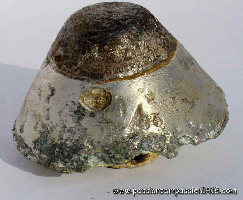
KZ 14 fuze.. Model made of aluminium and steel. With the following markings on the steel cap : 'KZ14 o R Stock & Co 15'. Aditional figures on the aluminium cone : '36'. |
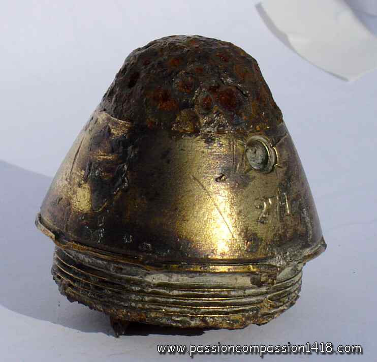
KZ 14 fuze.. Model made of brass and steel. marking '271' on the brass cap |
|
 |
 |
|
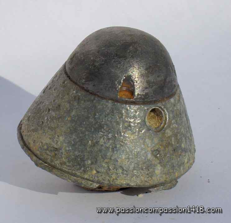
KZ 14 fuze.. Model in zinc alloy and steel. No visible markings |
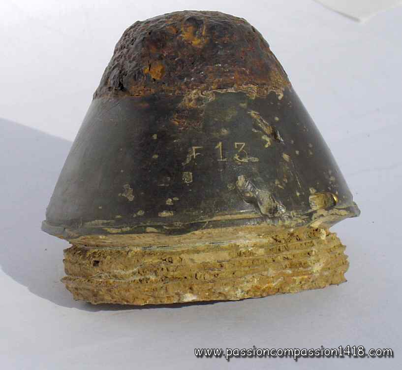
KZ 14 fuze.. Particularly slightly corroded piece in zinc alloy and steel. marking '513' on the zinc alloy body |
|
 |
 |
|
KZ 14 fuze.. This specimen is entirely made of brass. Observed on the Somme area. Markings 'HZ 14 - (Siemens Martin) 15 - 202' |
KZ 14 fuze. in brass, front view |
|
 |
 |
|
KZ 14 fuze.. Aluminium body and brass cap. Markings 'HZ 14 - ??? 15' |
KZ 14 fuze. made in brass, markings 'HZ 14 0 - SWN 15 - 381' |
|
 |
 |
|
KZ 14 fuze.. Several types of KZ14 fuzes, made in different material, commonly found on all the western front former battlefields |
KZ 14 fuze.. Wartime scheme |
|
 |
||
KZ 14 and KZ14 n/A fuzes. The specimen at the left side is a KZ14 n/A, that can be reckognized by the sharper profile of its upper cap |
||
 |
 |
|
KZ 14 n/A fuze. Specimen all made of zinc alloy. Characteristic shape with a sharper cap |
KZ 14 n/A fuze. A cross has been engraved on the top of the cap, indicating this is a modified fuze (hermetic bottom) for the use with gas shells |
|
Return at the top of the page |
||
HZ 14, HZ 14 Fb and HZ 14 Vorst. fuze |
||
 |
Inherited from the 1914 German fuzes generation based on the technology developped for the 'KZ 11' de l'obus universel comme la fusée percutante 'KZ 14' fuze of the light field gun, the HZ 14 fuze was the medel initially dedicated to the light field howitzers, but used afterwards with numerous other guns and howitzers. Just like its generation fuzes, it included the graze action arming system with two components (mobile primer pellet and percussion system safety by stem and gunpowder pellet), and the pecussion system (axial mobile graze pellet and static percussin pin, safety spring and safety stem blocking) that was the German state of the art in 1914. Its weight is still impressive when one can obeserve and manipulate a surviving brass specimen nowadays, and it is easy to imagine how deadly this piece could be alone, projected ahead after its shell burst ! Entirely made in brass at the beginning of the war, it was later built in different materials (steel, brass, zinc alloy) in order to save the copper alloys made precious by the allies blocus. The HZ 14 fuze was mounted on the high explosive or gaz shells of the :
Three versions followed the original model (HZ 14, introduced in 1914) that was too often subject to prematures in the howitzer bore :
|
|
HZ 14 Vorst fuze. |
||
 |
 |
|
HZ 14 fuze. Nice piece entirely made of brass. Markings 'HZ 14 - AEG 15 - 665'. |
HZ 14 fuze. Picture courtesy Luc Malchair. Markings 'HZ14 - AEG 15' |
|
 |
 |
|
HZ 14 Vorst fuze. Nice piece entirely made of brass. markings 'HZ 14 Sp15 - 864'. It is a 'vorst' (see the circular groove for the safety pin ring), although it is not mentionned by the markings |
HZ 14 Vorst fuze. This one suffered at the impact (just imagne the energy !). markings 'HZ 14 o Sp15 - 820' |
|
 |
 |
|
HZ 14 Fb fuze. 'Fliehb' model, that is with centrifugal security. Markings 'HZ 14 Flehb. O - SWN 15' |
HZ 14 fuze. View from below with the window for commucation of the flame to the detonator (missing) |
|
 |
||
HZ 14 fuze. From left to right : HZ 14, HZ 14 Vorst, HZ14 Fliehb., HZ 14 Vorst. Fliehb. All these pieces have been observed in Champagne |
||
 |
 |
|
HZ 14 Vorst fuze. This piece has been observed in Champagne. It is the one ('Vorst.') equipped with a safety pin. The fuze has been produced in 1916 and the cap is made in steel, saving brass. |
HZ 14 Fb fuze. Wartime scheme |
|
 |
||
HZ 14 fuze. Modern 3D reconstitution by Pascal CASANOVA (see the 3D Fuzes specific section of this website for numerous examples of his great work) |
HZ 14 Vorst fuze. Impressive transparent view by Pascal CASANOVA (see the 3D Fuzes specific section of this website for numerous examples of his great work) |
|
 |
||
HZ 14 fuze, dismantled to show the two cylinders hidden under the hat (inertia concutor and gunpowder blocked stem). Pictures courtesy Evo7125 |
||
Return at the top of the page |
||
Gr Z 16 |
||
 |
The German Navy introduced in 1916 new percussion fuzes for the high explosive shells of its 15 cm guns that were also used on the Army on improvised cariages or even in railway artillery. The particularity that came with this Gr Z 16 fuze was mainly consisting in the introduction of a 5 centrifugal bolts security, typixcal of some already existing Navy fuzes (such the bottom fuzes Spgr.m.K. of the 21 cm or 38 cm shells) and that will be found later in the 'Quick action fuzes Gr Z 17' and the 'fuzes for armor piercing 7.7 cm anti-tank fuzes'.
In this model, the static percussion pin was screwed on the top of the fuze body that might be either entirely in steel with a top screw, or in steel with a top brass cover including a screw. The mobile graze pellet with the primer cap was maintained out of range of the percussion pin thanks to a 5 rotating bolts on eccentic pivot in closed position at rest. This position was locked by an sliding arming ring that was tightening the bolts (or more precisely preventing the movements of one of them). A small safety spring was also inserted between the bolts 'door' and the percussion pin. At the shot start inside the barrel, the arming ring was pushed back under the effects of inertia, and was locked in that position by a staples blades system. This movement backwards was allowing the rotation of the bolts around their eccentric pivot under the effect of the centrifugal force progressively increasing with the accelaration of the shell inside the rifled gun bore, but these ones were still prevented from making this movement since they were pushed back on their support by the acceleration. This fuze designe was therefore particularily safe from shell bore explosions. At the bore exit at the muzzle, the acceleration suddenly stopped and only the centrifugal force remained. Its action was making the bolts rotate, opening the 'door' to the primer-bearing graze pellet. In flight, the small safety spring placed between the pellet and the percussion pin was the only protection against unwanted explosion. But it was very easily compressed by the shock at the arrival of the shell on its target, triggering the primer ignition and the transfer of its flame to the shell through an axial channel. The Gr Z 16 fuze also rarely existed in a version with an additional safety pin. It was in use wuth the high explosive shells of the :
|
|
Gr Z 16 Fuze. |
||
 |
 |
|
Gr Z 16 Fuze. Variant with a bras top hat |
Gr Z 16 Fuze. Zoom on the brass top part and the screw atached to the inside percussion pin |
|
 |
 |
|
Gr Z 16 Fuze. Rear view. See the still visible primer-bearing mobile graze pellet |
Gr Z 16 Fuze. No visible markings |
|
 |
||
Gr Z 16 Fuze. Wartime scheme |
||
Return at the top of the page |
||
LKZ 16 fuze (models m.V. or o.V.) |
||
 |
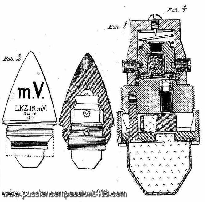
A new family of percussion fuzes was introduced in 1916 by the German Army, starting with the KZ 16 m.V. delayed percussion fuze dedicated to the 7.7cm FK 96 n/A fieldgun. This first model was quickly abandoned and replaced by the LKZ 16 having an identical inside mechanism, but with an elongated head for improved aerodynamic and penetration performances.
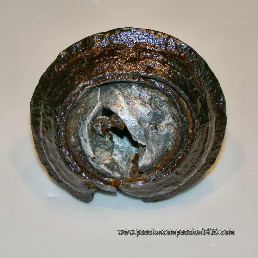
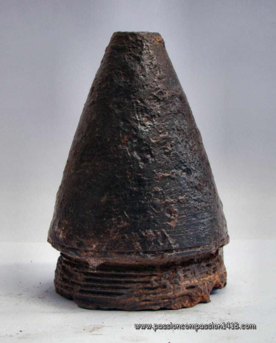
The LKZ16 fuze is quite commonly observed on the former battlefields. It appearance is very simple, since the usually visible part of the fuze is just a steel or zinc alloy cone. In fact, this part is only a steel top that covers the aluminium and brass percussion mechanism. The shape has good aerodynamics properties and was particularly designed for elongated shape shells with improved range. The fuze mechanism was a pure and simple graze action percussion system with a mobile graze pellet carrying the primer, and a static percussion pin protected by a safety spring. The fuze was secured by a double safety system activated by the centrifugal force :
Associated with a 23 gr. picric acid exploder, it was in use with the explosive projectiles of the
|
|
Fuze LKZ16. |
||
 |
 |
|
LKZ16 fuze. Conical steel hat, cracked by the landing shock |
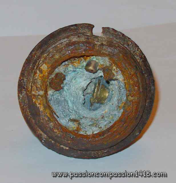
LKZ16 fuze. Dismantled specimen showing the room for the fuze brass mechanism |
|
 |
 |
|
LKZ16 fuze. Another piece. A careful cleaning let the machining marks and traces of the stamping appear...'LKZ16 o.V.' |
LKZ16 fuze. On this specimen, a difficult look at the markings 'LKZ 16 - 8 16'. On some specimens one can read 'o.V.' or 'm.V.' |
|
 |
 |
|
LKZ16 fuze. This cone has been broken by the impact and shows the aluminium enveloppe of the intern mechanism |
LKZ16 fuze. A bottom view of the same specimen with the intern mechanism still present. |
|
 |
 |
|
LKZ16 fuze. Remnants of the fuze brass mechanism |
LKZ16 fuze. Wartime scheme |
|
Return at the top of the page |
||
EKZ 16 fuze |
||
 |
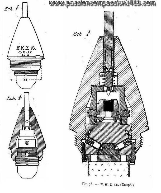
Although pretty similar at the first sight with the LKZ 16 because of the conical shape and dimensions, this fuze is indeed quite different. The EKZ 16 is indeed an simple effect super_quick model ('Empfindlicher Kanone Zunder'), whose explosion was occuring before the shell could dig into the ground, at the very first contact with the target. This kind of behavior was wanted when surface effects had to be maximised (anti-infantry or against barbwires), or for gaz shells.
In order to behave that way, a hollow steel or solid aluminium alloy percussion rod was located in the steel or zinc alloy fuze head axis. The rod projected around 1 inch from the fuze top, and had a percussion pin on its end inside the fuze body. When the shell landed on the target, the rod extension touched it instants before the shell body and was pushed back. This movement compressed the safety spring, and made the percussion pin meet the static pellet carrying the primer violently. Like the LKZ 16, the fuze mechanism was secured by a double safety system activated by the centrifugal force :
Equipped with a 23 gr. picric acid exploder, the EKZ 16 fuze was in use with the explosive shells and gaz shells (blue cross) of the
|
|
fuze EKZ16. |
||
 |
 |
|
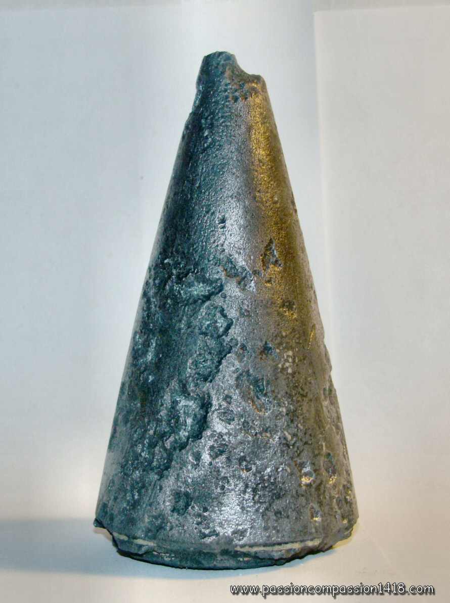
EKZ16 fuze. Conical steel hat, and upper hole for the percussion rod |
EKZ16 fuze. Zoom on the markings 'EKZ 16'. |
|
 |
 |
|
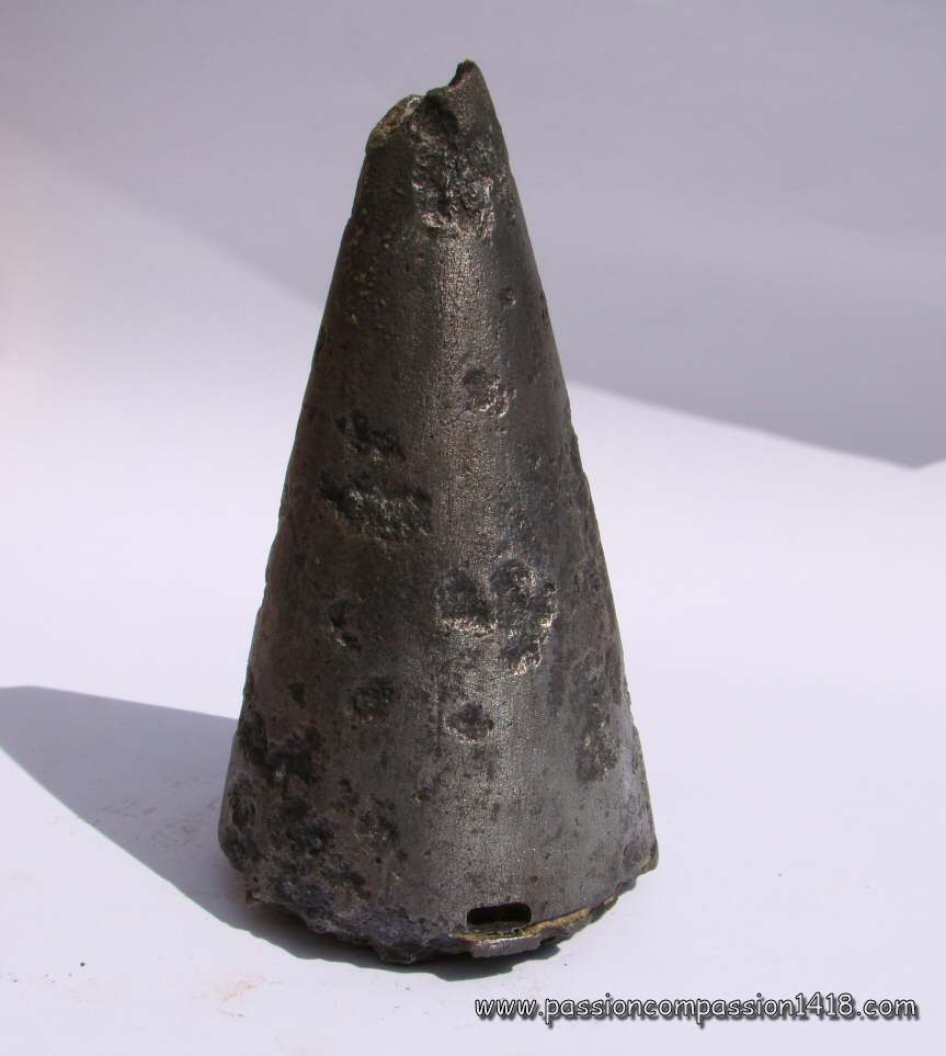
EKZ16 fuze. At a first glance, it might aas well be a EKZ 17 |
EKZ16 fuze. Lower view leaving no doubt on the identification : the cone is hollow, this is a EKZ 16 |
|
 |
 |
|
EKZ16 fuze. Surviving specimens observed in Champagne (Auberives) with remaining rods |
EKZ16 fuze. Wartime scheme |
|
Return at the top of the page |
||
EKZ 16 c fuze |
||
 |
The EKZ 16 c fuze was a streamlined version of the instantaneous percussion fuze EKZ 16, and having the same percussion rod in solid aluminium or hollow steel, and a similar interrnal mechanism. It was therefore also a single effect instantaneous (or super quick) fuze.
The EKZ 16 c fuze also had the adequate safety and arming systems :
The cone was made in zinc alloy, while the inner mechanism was made in steel and zinc alloy. Associated with a 23 gr. picric acid exploder, it was in use with the explosive shells of the
|
|
EKZ16c fuze. |
||
 |
 |
|
EKZ16c fuze. General view, no markings visible on that corroded zinc ally fuze |
EKZ16c fuze. Zoom on the top hole (percussion rod missing) |
|
 |
 |
|
EKZ16c fuze. Rear view with remnants of the fuze mechanism (in the middle the hole that could be blocked by the sliding lock to separate the percussion system and the relay charge) |
EKZ16c fuze. Wartime scheme |
|
 |
 |
|
EKZ16c fuze. Two examples. The one at the right still has its rod and is marked "EKZ16c ZU - AEG 18" - Courtsey Patrice Colin |
EKZ16c fuze. Cut'through showing the inner percussion body - Courtesy Patrice Colin |
|
 |
||
EKZ16c fuze. Enttirely dismantled, with a very nice view on the exploder safety sliding lock - Courtesy Patrice Colin |
||
Return at the top of the page |
||
KZ 16 f10cm K fuze |
||
 |
The KZ 16 f10cm K was a superquick percussion fuze, equipped with a long percussion rod protected at rest by a steel cap screwed on a thread.
Its internal organization was pretty similar to the one of the EKZ 16 c, and it was therefore a twin effect fuze as well (direct action and percussion) Just like in this latter, the KZ 16 f10cm K fuze was equipped with three different centrifugal safety systems : a two centrifugal bolts safety device for the direct action rod, another one for the graze pellet of the percussion system, and a centrifugal lock safety secured by two centrifugal bolts for the exploder. That fuze was in use with the high explosive shells of the
Exploder charge : 70 grammes of picric acid. |
|
KZ 16 f10cm K fuze. |
||
 |
 |
|
KZ 16 f10cm K fuze. Observed in Champagne, the steel head is in relative good state, while the zinc alloy and aluminium lower ring and body have nearly disappeared. |
KZ 16 f10cm K fuze. Upper view, with the hole equipped with a thread, where the percussion rod (disappeared) was situated. |
|
 |
 |
|
KZ 16 f10cm K fuze. Bottom view, showing the base notch where the detonator security drawer was sliding. |
KZ 16 f10cm K fuze. Side view. |
|
 |
 |
|
KZ 16 f10cm K fuze. Side view, some markings remains are hardly visible on the aluminium or zinc alloy base ring. |
KZ 16 f10cm K fuze. Wartime scheme |
|
Return at the top of the page |
||
HZ 16 fuze |
||
 |
The HZ 16 percussion fuze, with optionnal delay, is typical of the middle-war years, by its materials choice : the head and the detonator are in steel, the body and the mechanism are in zinc-alloy.
The classical percussion mechannism located under the steel cap (static percussion pin protected by a creep spring, mobile graze pellet carrying the starter and secured at rest by two centrifugal bolts) was similar to the one of the LKZ 16 fuze. It was communicating to the fuze tail of the fuze by two parallel channels. One of them was equipped with a black powder grain delay. An external selection stud allowed the shutting of the non-delayed channel when one wanted to use the delayed function ('m.V.' position). The HZ 16 fuze was equipped by an additional exploder safety system comparable to the one of the LKZ 16 fuze between the two flame communication channels and the exploder. It was composed by a drawer, sliding in a notch under the action of the centrifugal force : blocked at rest by two centrifugal bolts equipped with springs, it sealed the communicating channel between the detonator and the fuze head. Under the action of the shell spin, during its flight, it slided and put an exploding channel in the pyrotechnic axis. That fuze equipped the gas shells and explosive shells of the
|
|
Fuze HZ16. |
||
 |
 |
|
HZ16 fuze. Observed in champagne, see the goos preservation of the steel head, compared to the nearly-disappearing of the base zinc-ally ring. |
HZ16 fuze. Another specimen. The base zinc-alloy ring is unusually preserved and shows some markings. |
|
 |
||
HZ16 fuze. Two specimens side by side. The shape of the head of the one at left seems to have been changed by the explosion. Check at the base the sliding drawer notch for the detonator security system. |
||
 |
||
HZ16 fuze. Rear view, showing the excentric flame communicating channel to the detonator. |
||
 |
 |
|
HZ16 fuze. Another specimen in better condition (steel cap not deformed, base ring still there), but so corroded that no markings are visible. |
HZ16 fuze. Same specimen bottom view |
|
 |
 |
|
HZ16 fuze. Zoom on the the delay selector. |
HZ16 fuze. Wartime scheme |
|
Return at the top of the page |
||
EHZ 16 fuze |
||
 |
A simple look on the wartime schemes of the two fuzes demonstrates that the EHZ 16 fuze is a HZ 16 fuze to which a super-quick direct action rod system has been added. It then becomes a triple effect percussion fuze since it keeps the two percussion modes with delay and without delay of its predecessor, in addition to the additional super-quick behavior.
In order to obtain this transformation, the steel cap have been drilled in its axis, so that an aluminium rod could be introduced. The rod base was inserted into a mobile cylinder whose base was carrying the percussion pin, now mobile. The HZ 16 fuze safety systems were kept (centrifugal bolts safety system for the mobile graze pellet of the percussion system, and exploder centrifugal safety by a mobile lock), but a small modification of the percussion system design allowed its centrifugal safety system to act as well for retaining the super-quick system rod backwards movements at rest. The fuze was delivered to the batteries with the percussion rod separated, and a lead cap covering the top hole. A rope attached to the lead cover was carrying a tag saying « Draht mit Platte abreissen, Stecklift einstossen, so weit ungefärbt Sonst Blingänger» ("Insert the percussion rod along the whole painted part, or else the shell will misfire"). The rod was only inserted in the hole before the fire, and only when a super-quick behavior was needed. In the absence of that rod, the EHZ 16 was behaving exactly as a HZ 16 percussion fuze with or without delay depending on the external deay selection stud. The EHZ 16 fuze equipped the gas shells and explosive shells of the
|
|
Fuze EHZ16. |
||
 |
 |
|
Fuze EHZ16. Images courtesy Serge AMAND. Note the shape very similar to the HZ16 and the brass security mobile drawer |
Fuze EHZ16. Below view, similar to the one of a HZ16 fuze. Collection Serge AMAND |
|
 |
 |
|
Fuze EHZ16. Markings 'HZ 16 Zc Elster & Co' |
Fuze EHZ16. The percussion rod of this specimen seems to have melt inside its pit. |
|
 |
||
fuze EHZ16. Wartime scheme from a Belgian manual. Collection Serge AMAND |
||
 |
 |
|
fuze EHZ16. Another specimen. See the markings on the side of the ring. Pictures courtesy Luc Malchair |
fuze EHZ16. Rear view. Pictures courtesy Luc Malchair |
|
 |
||
fuze EHZ16. Rear view on two specimens, with the disappeared drawer location. |
||
Return at the top of the page |
||
EKZ 17 fuze |
||
 |
At fisrt sight, the EKZ 17 fuze looks identical to the EKZ 16 fuze, but the inner mechanisms of the two models are completely different. The new fuze is still a super quick model thanks to the presence of a direct action rod system, but the design has been simplified to the extreme limit, most probably to save costs and production time in this late period of the war, when resources became more and more rare.
The mechanism is reduced to its stricty minimum : a magnesium allot rod is inserted into a hole drilled axially inside a massive cone. It carries the percussion pin on its base, placed in front of a static primer directly mounted with a detonator inside the exploder. Thge percussion pin and the primer are kept separated at rest by a safety creep spring. The only arming system is a simple lateral centrifugal lock pushed at rest into a hole at the base of the rod by a spring, and retracting in flight under the action of the shell spin. The exploder had no specific safety device. It was therefore a simple effect fuze (strictly super quick without any additional percussion behavior). The massive ogive was entirely made in zinc alloy, or by assembly of a pig iron upper part and a zinc alloy base either by a thread ('EKZ 17 Zi E Gew') or by a dovetail joint made at pouring time ('EKZ 17 Zi E Guss'). The fusée EKZ 17 fuze equipped the high explosive and gaz shells (green cross, yellow cross and bluie cross) of the :
It was delivered to the batteries with an attached 23 gr picric acid exploder, and with the rod aside and the fuze hole closed by a removable lead seal. |
|
Fuze EKZ17. |
||
 |
 |
|
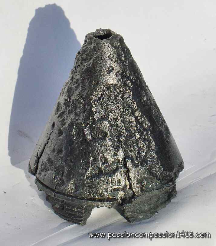
Fuze EKZ17. Highly corroded zinc alloy conical head |
Fuze EKZ17. Upper view with the percussion stem (disappeared) housing. |
|
 |
 |
|
fuze EKZ17. Typical shape. A first clu for the identification is the existence of the radial tunnel of the centrifugal safety spring (not visible on this picture) |
fuze EKZ17. This lower view gives a second clue for the identification, since the head is not hollow like it should be for a EKZ 16. |
|
 |
 |
|
fuze EKZ17. The surface is badly corroded, but the markings are still slightly visible : 'E.K.Z.17 - ??? 17 - 400' |
fuze EKZ17. Wartime scheme |
|
 |
 |
|
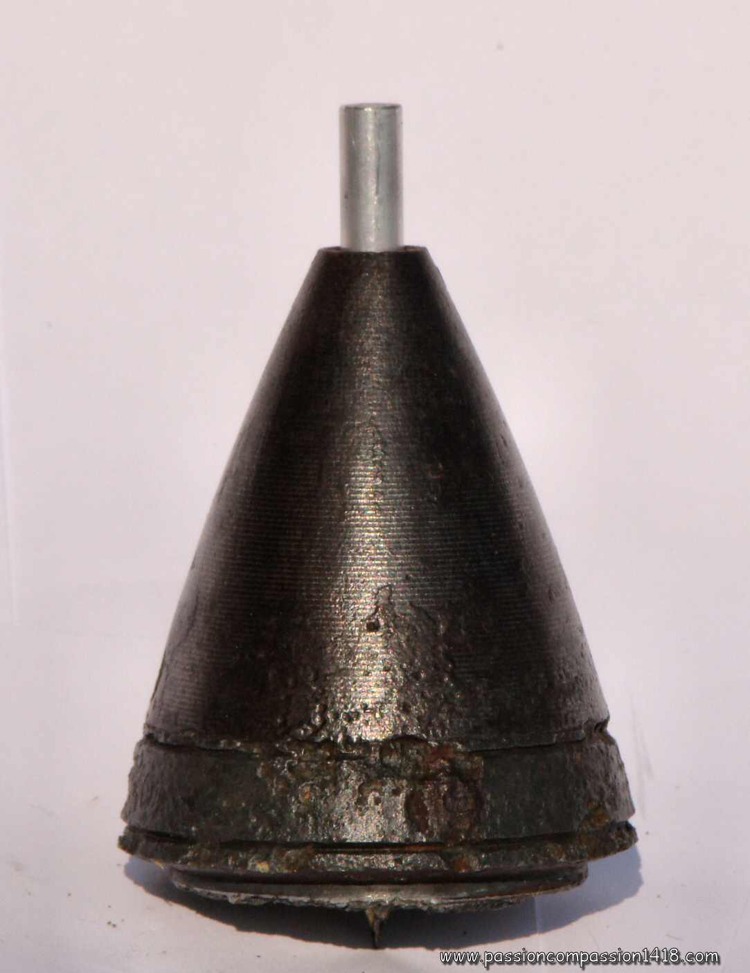
Fuze EKZ17. This specimen is in pretty good shape. Steel body, the base thread has disappearedThe rod is factice (aluminium bar). No visible markings. |
Fuze EKZ17. Same specimen, base view, showing the impressive percussion pin. |
|
Return at the top of the page |
||
EHZ 17 fuze |
||
 |
The EHZ 17 fuze is the howitzer dedicated version of the super quick EKZ 17 fuze. The internal devices were identical. Only the external dimensions were different, with a rounder head shape and the 57.5mm thread diameter adapted to the light field howitzer shells.
The EHZ 17 fuze equipped the gas shells and explosive shells of the
A variant is known with a mobile primer pellet 'EHZ 17 Bew' ('Beweglicher schlagbolzen' - mobile primer), therefore giving an additional percussion behavior (double effect fuze) |
|
EHZ17 Fuze |
||
 |
 |
|
EHZ17 Fuze. Percussion rod removed. Images courtesy of Serge AMAND |
EHZ17 Fuze. Percussion rod placed. Collection Serge AMAND |
|
 |
 |
|
EHZ17 Fuze. Collection Serge AMAND |
EHZ17 Fuze observed in Champagne. |
|
 |
 |
|
EHZ17 Fuze. Zinc alloy material pretty corroded but part of the marking is still visible '17' |
||
 |
||
EHZ17 Fuze mounted on a 10.5 cm ogive; view on the screw obturating the channel of the centrifugal lock system |
EHZ17 Fuze. Rear view, the detonator has bursted and is torn |
|
 |
||
EHZ17 Fuze. Wartime scheme from a Belgian manual. |
||
Return at the top of the page |
||
Gr Z 17 fuze |
||
 |
The Gr Z 17 fuze, as a instantaneous apparatus triggered by a percussion hollow rod, secured at rest by a inertia centifugal bolts system was a brand new design that will become preponderant after WW1.
This safety system that had been introduced earlier by the Navy, particularily in some heavy caliber bottom fuzes and in the 'Gr Z 16 fuze',was made of a ring of 5 imbricated centrifugal bolts that were rotating on an axis under the action of the shell spin. This movement was only made possible after the shell launch since these locks were retained by a ring until the departure shock momentum made it move backwards. Once the safety system has been desactivated, the percussion pin attached to the head mobile brass rod was separated from the base starter-bearer just by a simple safety spring. The top head plug was either made of brass or steel, while the body was in steel. A variant Hb Gr Z 17 is akso known, with a cylindrical top plug. Used with an exploder, it equipped the gaz shells and explosive shelles of the :
|
|
Fuze Gr Z 17. The percussion rod is fake and replaced by a rifle cartridge for illustration purposes. barely visible markings : '15' on one side, 'Gr.Z17 - K.18' on the other side |
||
 |
 |
|
Fuze Gr Z 17. This specimen body shape has been heavily changed by the shell explosion, but despite the enlarged base, the fuze type is reckognizable |
Fuze Gr Z 17. Seen from above showing the hole for the percussion pin in the top plug. |
|
 |
 |
|
Fuze Gr Z 17. Bottom view. The inner parts have disappeared but the percussion rod is still there. |
Fuze Gr Z 17. Bottom view |
|
 |
 |
|
Fuze Gr Z 17. Some markings hardly visible 'Gr Z 1...' |
Fuze Gr Z 17. Wartime scheme |
|
Return at the top of the page |
||
Aufschlagzünder mV fur K.Gr. 15 m.P. fuze |
||
 |
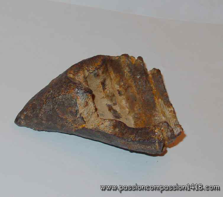
Faced to the irruption of British tanks on the Somme battlefield as soon as summer 1916, the Germans had to quickly invent the corresponding anti-tank weapons. Re-inforced explosive charge grenades, landmines and dedicated high power rifles were distributed to the infantrymen until the end of the war, but early fights experience showed that conventional high explosive shells of the commen 7.7cm fieldguns could 'do the job' pretty well if hitting the target at sensitive places under good ballistics conditions (speed, angle).
The German Army required the developement of a specific armor-piercing 77mm shell on the basis of the conventional high explosive 7,7cm K Gr 15, named 7,7cm K Gr 15 mP ('mP' ='mit Panzerkopf'). This high explosive shell, theoritically efficient up to a 5000 m range but practically used within distances lower than 1500 m, was also containing a smoke generating composition in its bottom. It was topped by a massive extra-hard quenched steel cone able to pierce 20mm armor plates, and contained a specific delayed percussion fuze that triggered the explosion once inside the vehicle. The Aufschlagzünder mV fur K.Gr. 15 m.P. fuze had an aluminium body. Its intern mechanism was a percussion-type one, with a centrifugal safety device similar to the one of the 'Gr Z 16 fuze', and a small delay both mechanical (the starter flame had to follow a sinuous path) and pyrotechnic (with a compressed black powder disc). The fuze and cone thread diameter was 51.5mm. Equipped with a 25g TNT exploder, this fuze was used with the armor-piercing explosive shells of the
|
|
Aufschlagzünder mV fuze. |
||
 |
 |
|
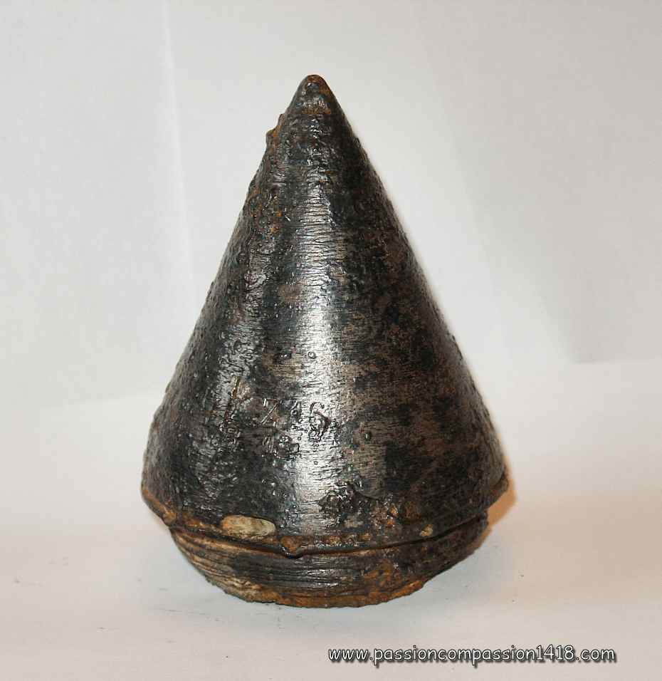
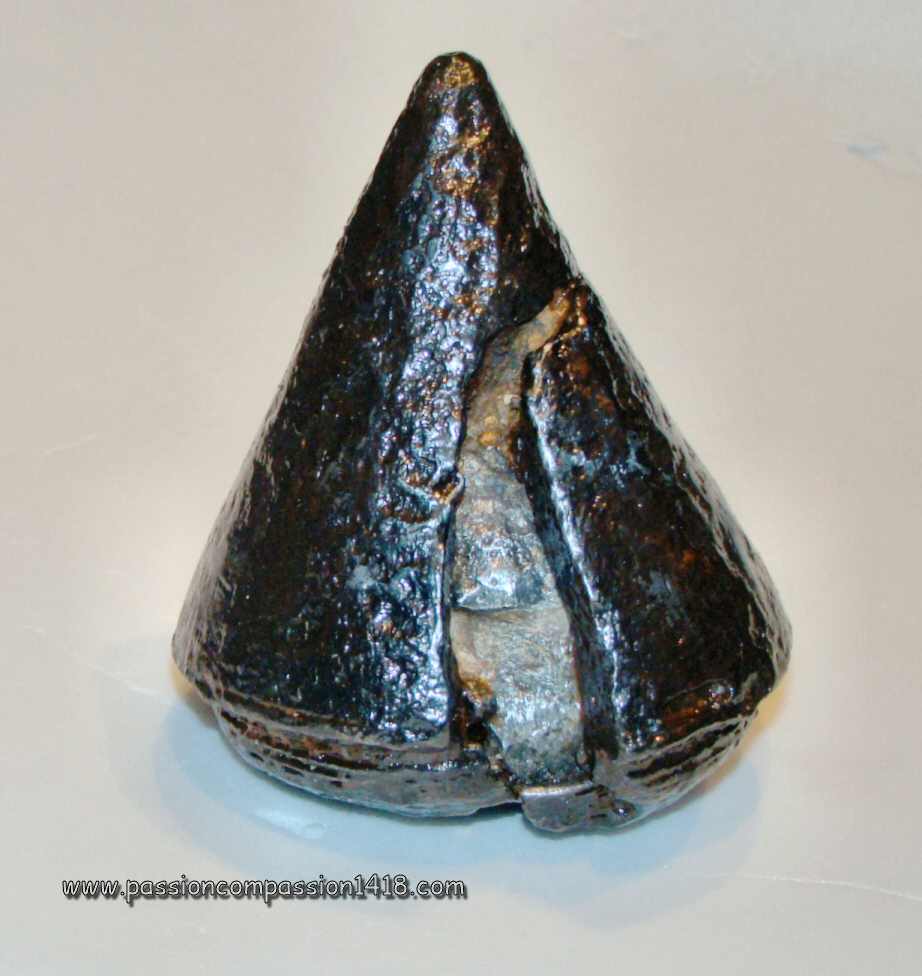
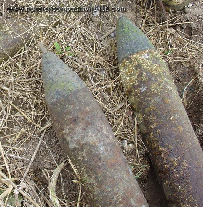
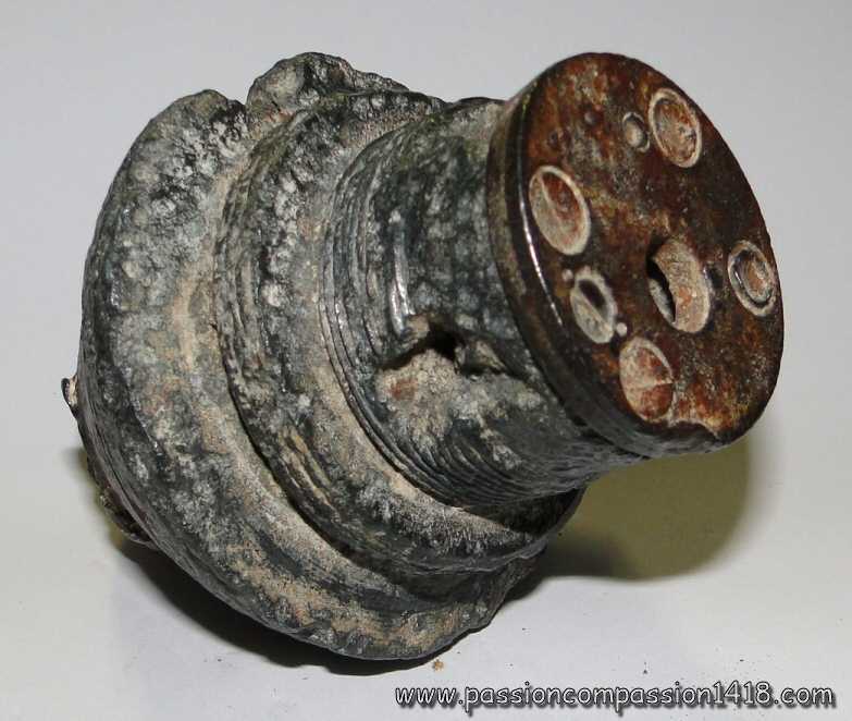
Aufschlagzünder mV fuze. The picture only shows the hardened steel massive cone protecting the fuze. |
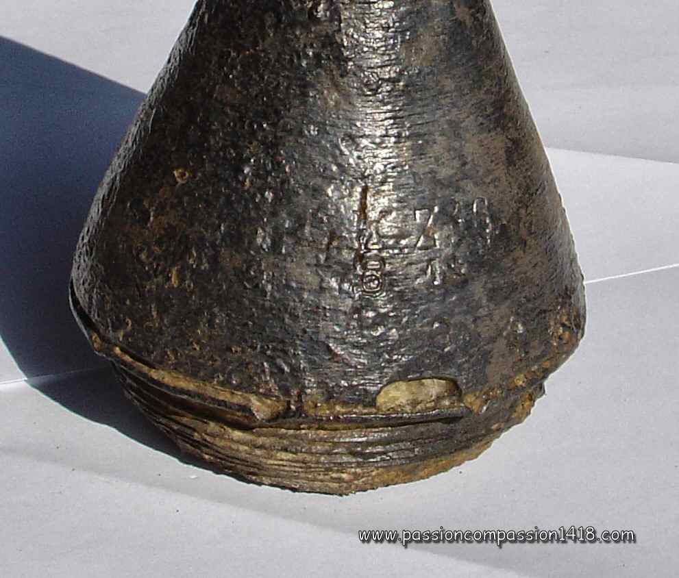
Aufschlagzünder mV fuze. Unidentified markings on the cone top. |
|
 |
 |
|
Aufschlagzünder mV fuze. The same armor-piercing shell nowadays. Picture courtesy Serge AMAND |
||
 |
||
Aufschlagzünder mV fuze. The 7,7cm K Gr 15 mp anti-tank shell impressive reconstitution by Pascal Casanova (see the 3D Fuzes specific section of this website for numerous examples of his great work) . |
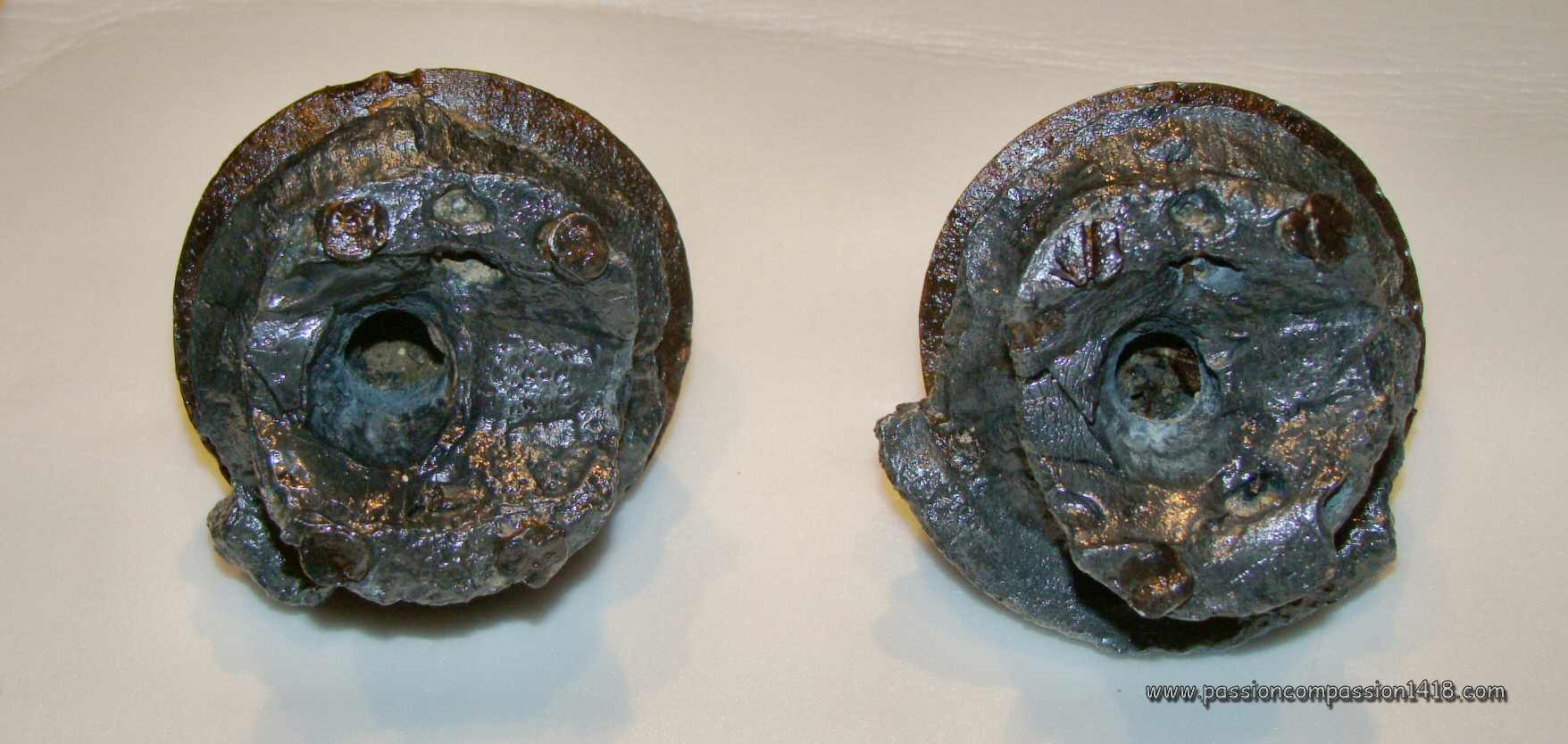
Aufschlagzünder mV fuze. Bottom view showing the fuze room (deformed bu the explosion). |
|
 |
||
Aufschlagzünder mV fuze. Internal fuze (seen on Delcampe auctions website) |
||
.jpg) |
 |
|
Aufschlagzünder mV fuze. 3D cut-out by Pascal Casanova (see the 3D Fuzes specific section of this website for numerous examples of his great work) |
Aufschlagzünder mV fuze. Wartime scheme. |
|
Return at the top of the page |
||
Schr Z c/73 Fuze |
||
 |
In 1863, the Hauptmann Richter, of Spandau arsenal near Berlin, starts the design of a revolutionary pyrotechnic time mechanism, based on the variation of the length of a compressed gunpowder circular track by the rotation of a revolving disc. The 'Richtersche Zeitzunder' (Richter time fuze) is adopted by the German Army in 1869, and will participate to the Germano-French war in 1870 at the side of its two daughters, the time fuzes '8 cm FeldSchrapnellzünder c/70' and '9 cm FeldSchrapnellzünder c/70'. This will contribute to the artillery technological advance that was one of the major components of the German victory.
From the c/70 marks, the technique of separating the time system, definitely mounted on the shell at the factory, and the graze action arming system (concutor) included inside a removable threaded plug ('BolzenSchraube 70') and assembled just before the use was adopted for safety reasons. This modification of the Richter system gave birth to several time fuzes including the SchrapnelZunder c/71 with discs, and the FeldSchrapnellZunder c/73 with a single disc, afterwards associated to a new 'BolzenSchraube 73', and all having the same reckognizable truncated cone profile. |
|
Schr Z c/73 Fuze. |
||
 |
 |
|
Schr Z c/73 Fuze. Mounted on 3 legs as a trench souvenir. View from above on the removable plug containing the concussion system (Boldenschraube). |
Schr Z c/73 Fuze. marking 'F 84'; The Combustion gasses exhaust window has been filled in. |
|
 |
 |
|
Schr Z c/73 Fuze. Graduations from 2 to 25 hectometres./font> |
Schr Z c/73 Fuze. View from below, with the flame communication channel to the shell gunpowder; The shell thread has been sawed |
|
 |
||
Schr Z c/73 Fuze. Modern scheme - picture taken on the good forum www.odkrywca.pl. |
||
Retour en haut de page |
||
Schr Z c/84 Fuze |
||
 |
The time fuze SchrapnellZunder 83 appeared in 1883, equipped with a new concussion system in removable plug 'BolzenSchraube 83'. Still inspired by the Richter system and derivating directly from the 'FeldSchrapnellZunder c/73' associated with a BolzenSchraube 73. Its profile was however radically different with a mobile upper revolving disc having a diameter equal to the lower fixed disc, and an upper blocking bolt.
Once assembled, the top plug concussion system, with a static lower percussion pin and a mobile pellet bearing the starter, allowed the shell initial acceleration to ignite the gunpowder circular track located under the mobile revolving disc and communicating to the fuze tail by a hole in the lower static disc. The position of this hole compared to the gunpowder track was tuned by rotating the revolving upper disc and gave the exact time needed to communicate the flame to the shell main explosive via a gunpowder room located inside the fuze hollow tail. The upper disc was graduated in hectometres from 0 to 35 with 200 m steps. Another range of graduations was engraved in the static lower disc and gave the equivalent value in seconds of flight, from 0 to 14. This secondary graduation was found useless (and most probably source of mistakes), therefore a simplified model was introduced in 1884 keeping only the upper graduations in hectometres in the upper rotating disc. This version was named the time fuze SchrapnellZunder 84. |
|
Schr Z c/84 Fuze. |
||
 |
 |
|
Schr Z c/84 Fuze. View from above on the removable plug containing the concussion system (Boldenschraube). |
Schr Z c/84 Fuze. marking 'F 84'; graduations from 3 to 35 hectometres. |
|
 |
 |
|
Schr Z c/84 Fuze. Combustion gasses exhaust window |
Schr Z c/84 Fuze. View from below, with the flame communication channel to the shell gunpowder |
|
 |
||
Schr Z c/83 Fuze. Modern scheme - picture taken on the good forum www.odkrywca.pl. This initial model shows seconds graduations on the lower static disc |
||
Retour en haut de page |
||
Dopp Z c/86 fuze |
||
 |
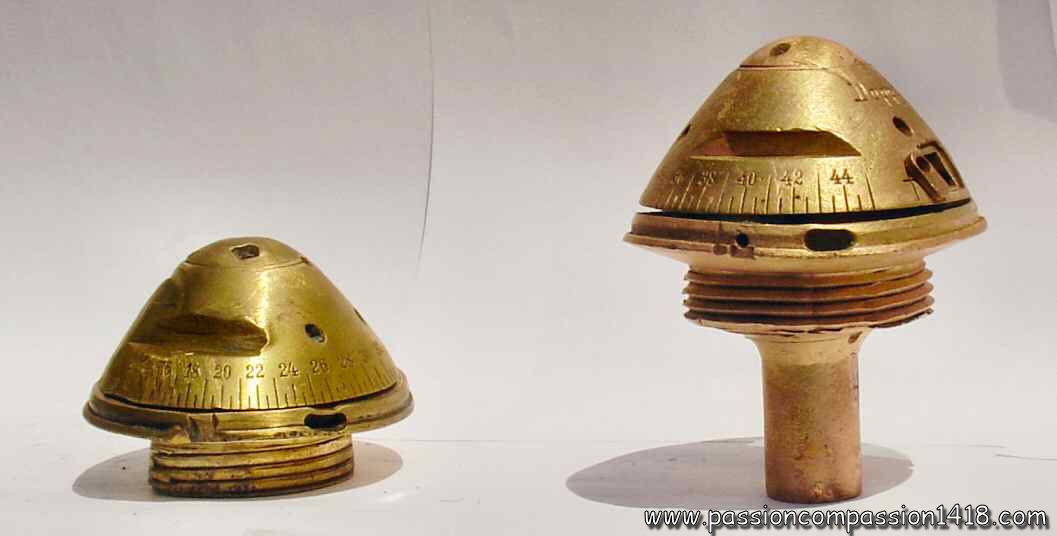
Appeared in Germany in 1869, the Richter system revolutionned the fuzes technique with the introduction of revolving discs pyrotechnic time mechanisms. It evolved for about 20 years, giving birth to several types of time fuzes with growing complexity, before the apparition of the next generation in 1891. A very important evolution step of this evolution was reached in 1885 : until then, the Richter system evolutions only created time fuzes, but that year a new removable plug, completely redesigned, allowed to a new fuzes evolution to behave as 'double effect' fuzes, that is Time and Percussion.
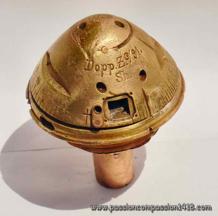
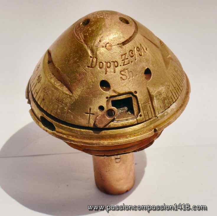
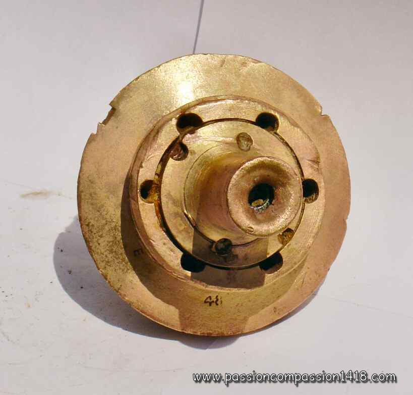
This new removable plug, called 'DoppZdrSchr c/85' ('DoppelZundersSchraube c/85') was protected under a steel cap giving it a characteristic egg profile. It included both the concussion system and a percussion system copied from the 'Gr Z c/80' percussion fuzes. It was assembled before the shooting on 1- or 2- revolving discs time system bodies, similar to the new profile of the time fuzes 'Schr Zdr 83 and 84'. A second version of removable double effect plugs version named 'DoppZdrSchr c/86' ('DoppelZundersSchraube c/86') introduced the new graze action mobile pellet and percussion pin mounted on a transversal bridge that was later to equip several fuzes beginning with the time and percussion 'Dopp Z 91'. The fuze removable plug had mushroom shape. This upper mobile mass head included two starters placed in front of two percussion pins mounted on the static body and protected by a tulip shaped spring. The departure shock made the 'mushroom' head move back and flatten the spring, causing the starter to be triggered. The resulting flame was used both for lighting the compressed gunpowder track contained into the rotating discs time system, and to burn a big compressed gunpowder pellet located into the upper part of the plug tail and blocking the movements of the percussion graze action mobile pellet bearing the main starter. When the percussion behavior was acting, the landing shock propelled the freed percussion pellet on the percussion pin mounted on a static transversal bridge, and the flame was transmitted to the shell by a hole on the base of the plug tail. The single rotating disc time system was a slight evolution of the one of the 'Schr Zdr 83 and 84', with hectometres graduations on the upper mobile disc (from 3 to 31.5), and equivalent graduations in combustion time on the lower static disc (from 1 to 13 seconds). These latters had been removed on the SchrapnellZunder 84 version, and were also sometimes masked under a black vernish on the new time and percussion fuzes. Whe the time behavior was acting, the portion of compressed gunpowder track burnt until the end of the selected duration, then the flame was tranmitted to the shell via 6 channels machined inside the time fuze body. This evolution gave birth to two types of fuzes : the 2-discs 'Dopp Z c/85' time and percussion fuzes, and the single disc 'Dopp Z c/86' time and percussion fuze. This last one is by far the best known and was still sometimes used in 1914 on the shrapnell projectiles of the old
A very last evolution of the Richter system occured in 1888, with the mounting of a M 1888 exploder on the 1886 type time and percussion fuze body, mounted in the factory on the shell and still only receiving the removable concussion / percussion plug just before fire. The last pieces of this 'Dopp Z c/88' time and percussion fuze, ultimate evolution of the Richter systems with removable plugs, were used until 1916 mostly in a percussion behavior with the high explosive shells of the old
|
|
Dopp Z c/86 fuze |
||
 |
||
Dopp Z c/86 fuze. The left one still has its steel protecting cap. |
||
 |
||
Dopp Z c/86 fuze. Dismounted 'DoppelZundersSchraube' removable concussion / percussion plugs. The right one was triggered, since the upper part flattened the spring by moving back under the action of the shock of departure. |
||
 |
||
Dopp Z c/86 fuze. Rear view on the 'DoppelZundersSchraube', the 6 peripheric channels were dedicated to transmit the xoncussion system flame to the compressed gunpowder track of the revolving discs time system. |
||
 |
 |
|
Dopp Z c/86 fuze. Zoom on the time system, the lower static disc is graduated in combustion time (1 to 13 seconds - 'Sek.'). |
Dopp Z c/86 fuze. Zoom on the time system, the upper rotating static disc is graduated in flight distance (3 to 31.5 hectometres - 'Feld.'). |
|
 |
 |
|
Dopp Z c/86 fuze. Rear view with the 6 channels machined in the main body and dedicated to transmit the flame to the shell when acting as a time system, ant the central channel used by the flame of the percussion system located inside the DoppelZundersSchraube tail. |
Dopp Z c/86 fuze. War time scheme |
|
Retour en haut de page |
||
Dopp Z 91 fuze |
||
 |
Following and inheriting some of the technical devices of the Dopp Z c/88 fuze (including its percussion system), the Dopp Z 91 starts a new generation of German time and percussion fuzes by integrating the graze action arming system into the time fuze body, previously removable in a top plug to be mounted just before use.
Single disc time and percussion fuze made in brass and graduated from 3 to 45 hundreds of metres, this Dopp Z 91 fuze is also the first German fuze that introduces the graze action arming system based on a massive gunpowder pellet and a percussion pin protected by a tulip spring, first appeared under a primitive form with the 'Dopp Z 86' fuze, and that will be seen again in the 'Dopp Z 92', 'Gr Z 92', 'Dopp Z 92 nF', 'Gr Z 96 et Gr Z 96/04', and 'Gr Z 04' fuzes. The graze action arming system operated both for the arming of the percussion system and the ignition of the time system. It was secured with a two rods safety pin, to be removed before the shot. This liberated the movements the graze arming system, whose massive mobile graze pellet (bearing the primer) slided back under the discharge momentum action and hit a fixed percussion pin protected at rest by a spring cap having the shape of a tulip (sometimes compared to a crown) flattened under the pellet pressure, setting fire to a big gunpowder pellet. This pellet combustion made possible the movements of the percussion system graze pellet located in the fuze tail. At impact, the primer-bearer cylinder was propelled against a percussion pin fixed to a transverse bridge. The resulting flame was directed backwards through the fuze tail base hole, and bursted the exploder (with high explosive shells) or communicated with the rear gunpowder chamber of the shrapnel shells via the axial tube. The gunpowder pellet combustion flame also set fire to the gunpowder circular track of the time system, setup to the needed time by rotation of the graduated head to the desired range. After this time, the flame was communicated to the exploder gaine (for high explosive shells) or to the rear gunpowder chamber (for shrapnel shells) by 6 holes located on a circle around the fuze tail base. This fuze was designed for the high explosive ('Gr' = Granate - Obus explosif) or shrapnel shells of the
| |
Fuze Dopp Z 91. |
||
 |
||
Fuze Dopp Z 91. Two specimens. The left one is coming from a mounting as an inker, shown below, markings 'Dopp Z K / 91 - J'. The right one has been found in the Somme, markings 'Dopp Z c / 91 - Sb - Wd - 4 - 94 - E - 48' |
||
 |
 |
|
fuze Dopp Z 91. Lateral view, showing the markings, and the small lever on the gaz window, in 'up' position. |
fuze Dopp Z 91. Same view, with the small lever in 'low' position |
|
 |
 |
|
fuze Dopp Z 91. View from behind, with the 6 circular holes for the time-system caused ignition, and central hole in the tail for the percussion system caused ignition |
fuze Dopp Z 91. View from above |
|
 |
 |
|
fuze Dopp Z 91. This specimen has been transformed into an inker by a WW1 veteran |
fuze Dopp Z 91. Wartime scheme |
|
Return at the top of the page |
||
Dopp Z 92 fuze. |
||
 |
The two discs time and percussion fuze Dopp Z 92 was an evolution of the Dopp Z 91 fuze. Like this latter, it was using the same classical graze action arming system secured by a two rods safety pin and based on a massive gunpowder pellet and a percussion pin protected by a tulip spring appeared in its primitive shape in the old Dopp Z 86 fuze, and the tail graze percussion system based on a cylindrical graze pellet bearing a starter and a static percussion pin transverse bridge.
Just considering these components needed for the percussion fuze behaviour (selected by setting the graduated ring onto the roman cross), the Dopp Z 92 fuze was therefore almost identical to the same generation percussion fuze 'Gr Z 92'. The major evolution compared to the Dopp Z 91 was given by the existence of two time rings instead of one, the lower one only being graduated (from 1 to 28 seconds for the first version). Entirely made of brass, it was developped in several versions :
This fuze and its versions were extensively used with numerous projectiles during WW1. It was mounted on shrapnel and high explosive shells of the :
|
|
Fuze Dopp Z 92. |
||
 |
 |
|
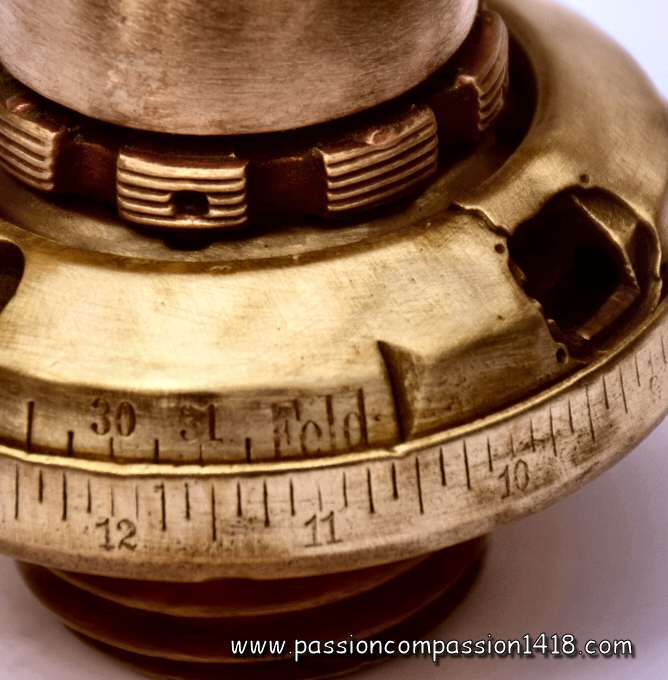
Fuze Dopp Z 92. Markings 'Dopp Z 92 Sp16 - 6', observed near the Mort-Homme at Verdun, and carefully cleaned. Rotating disc indexed on a 20 seconds time setting |
Fuze Dopp Z 92. Same specimen, detail showing the holes for gunpowder burning gasses escape |
|
 |
 |
|
Fuze Dopp Z 92, original design |
Fuze Dopp Z 92, original design. The graduation ranges from 1 to 28 seconds. |
|
 |
 |
|
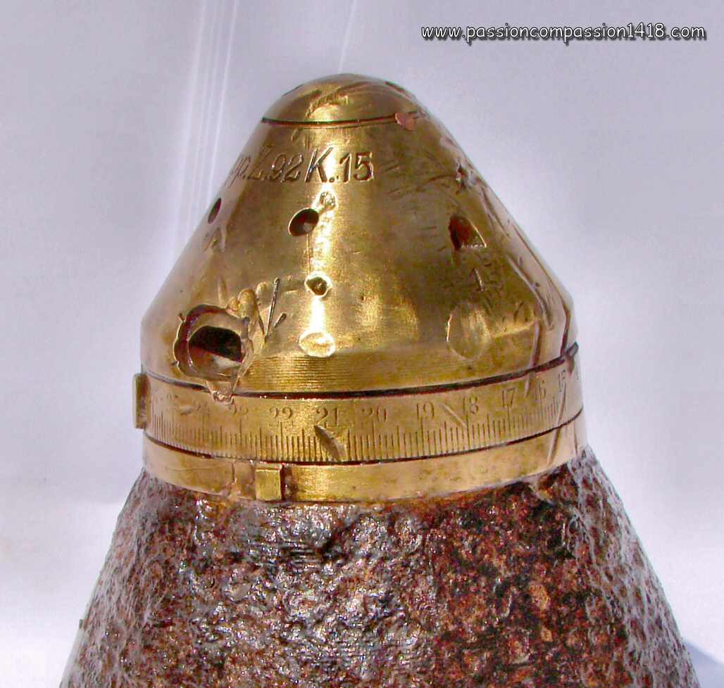
Fuze Dopp Z 92 K15. |
Fuze Dopp Z 92 K15. The graduation ranges from 1 to 26 seconds |
|
 |
 |
|
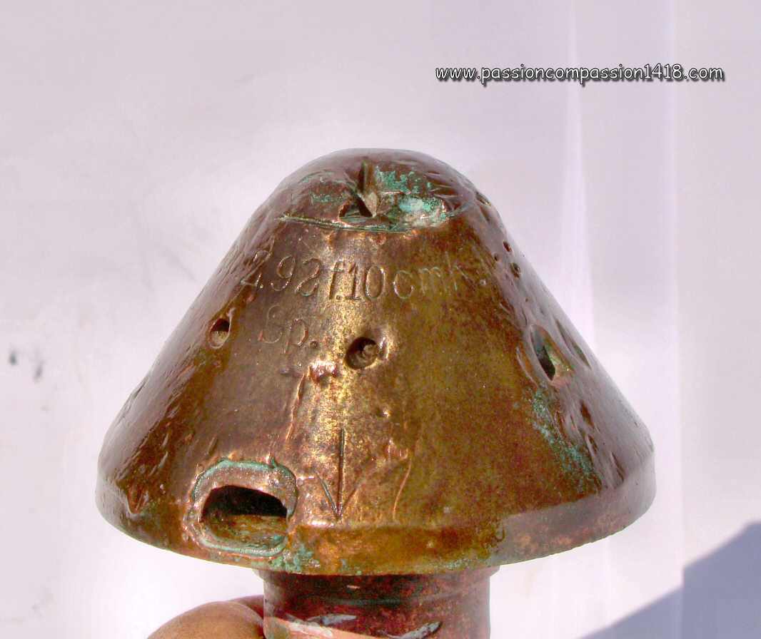
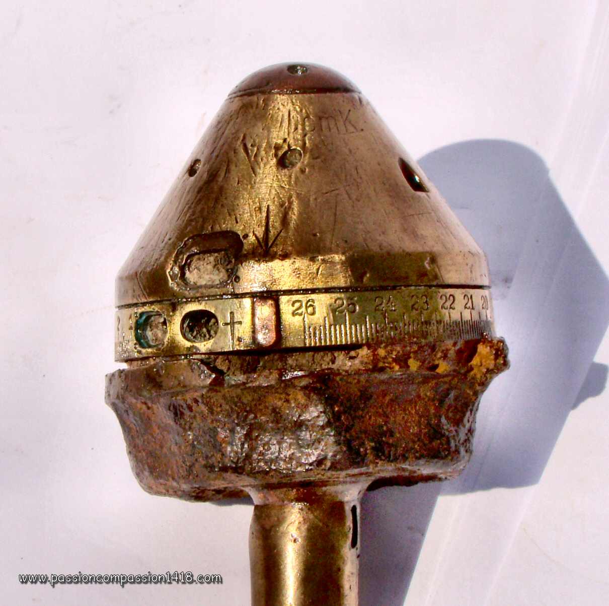
Fuze Dopp Z 92 f10cm K. |
Fuze Dopp Z 92 f10cm K. The graduation ranges from 1 to 26 seconds |
|
 |
 |
|
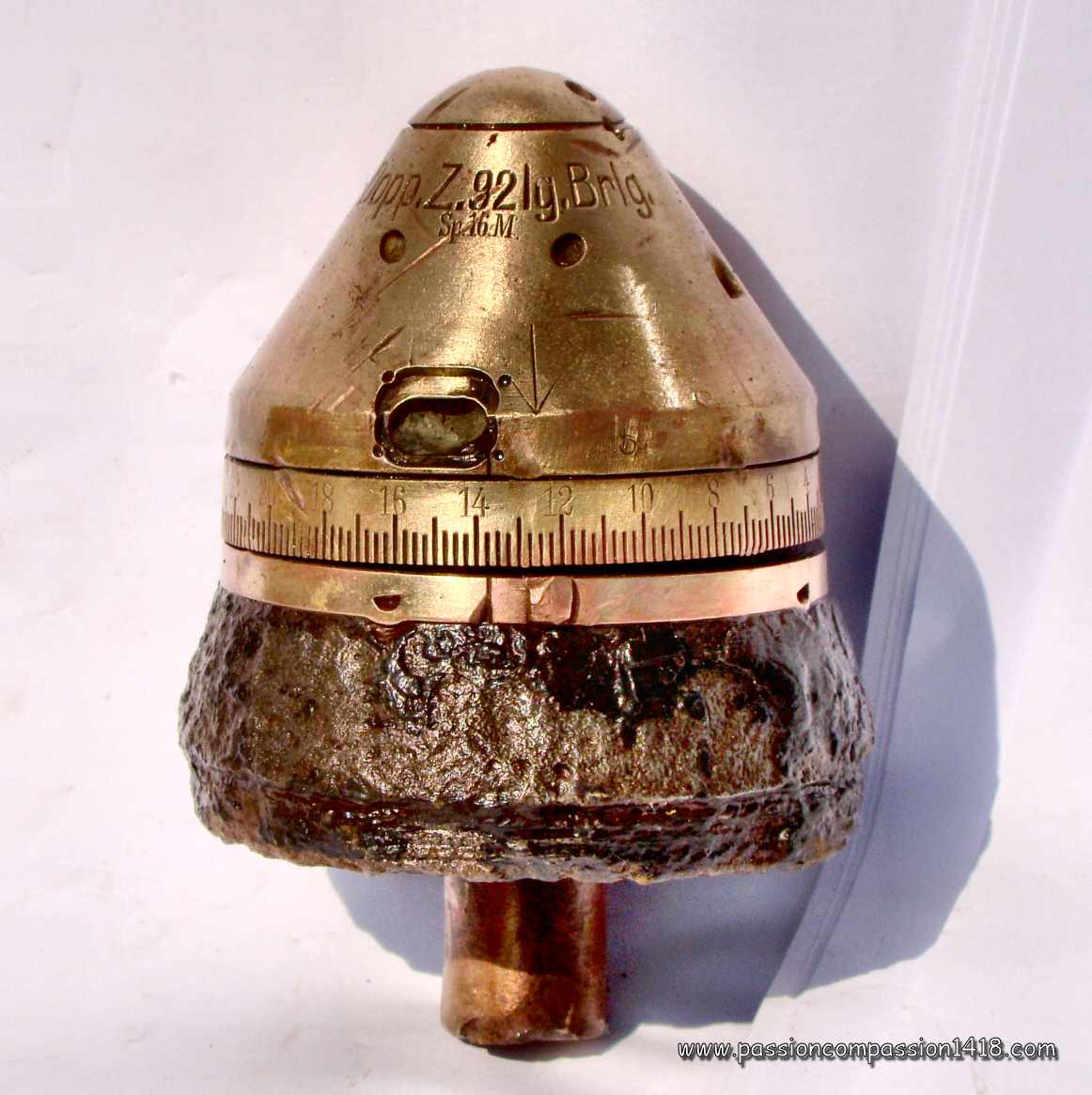
Fuze Dopp Z 92 lg Brlg. |
Fuze Dopp Z 92 lg Brlg. The graduation ranges from 2 to 41 seconds |
|
 |
 |
|
Fuze Dopp Z 92 lg Brlg o.Az. AA ammo with lont burning time and without percussion system; This fuze name stamp becomes so long.... |
Fuze Dopp Z 92 lg Brlg o.Az. ....that it needs two pictcures to get it complete ! |
|
 |
 |
|
Fuze Dopp Z 92 FH. Antique copy of this very rare version, mounted on a 1905 FussArtillery 2nd Regiment reservist mug. |
Fuze Dopp Z 92 FH. This ancient fake fuze is hollow and made in some kind of lead, but the markings seem right with the time disc graduated from 5 to 56 hectometers |
|
 |
 |
|
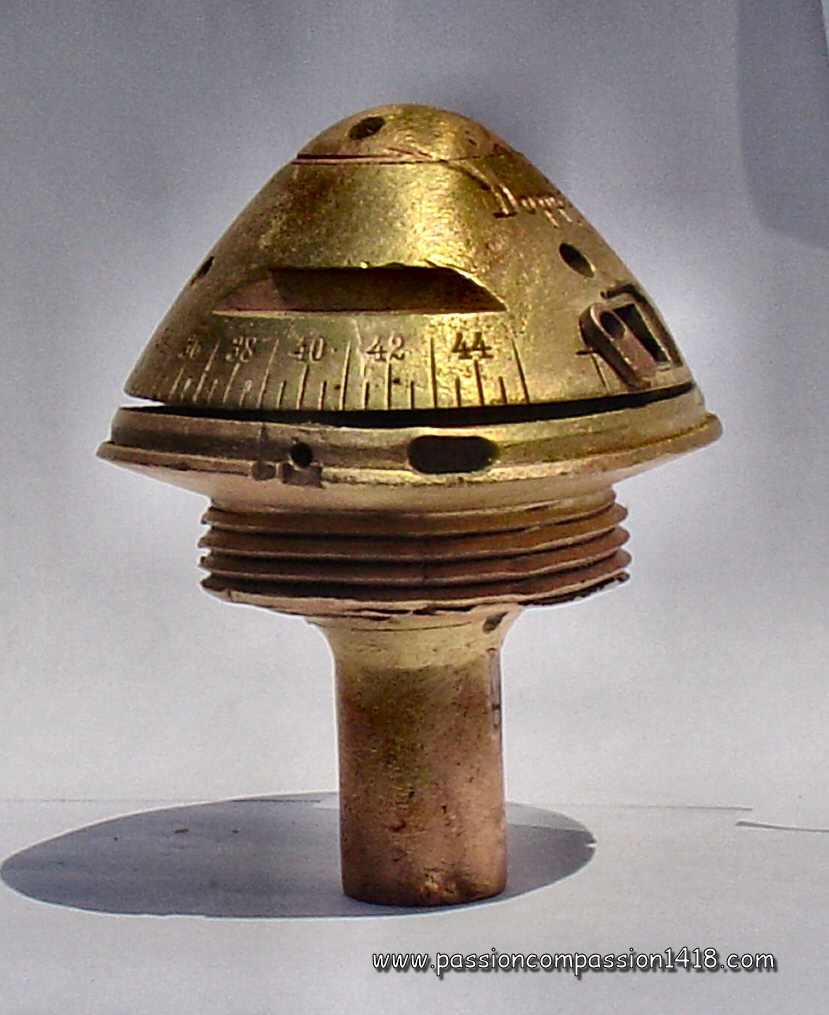
Fuze Dopp Z 92. These pieces, respectively mounted on a shell head of approximate caliber 105 mm (markings 'Dopp Z 92 - Sp16 - 13', set on 16 seconds) and 135 mm (markings 'Dopp Z 92 - Sp16', set on 18 seconds), have been observed in Verdun, near the Mort Homme. |
Fuze Dopp Z 92. View from below, showing the shrapnell balls still glued, surrounding the remainings of the fuze tail |
|
 |
||
Fuze Dopp Z 92, dismantled disks. Picture courtesy J Faulkner |
||
 |
 |
|
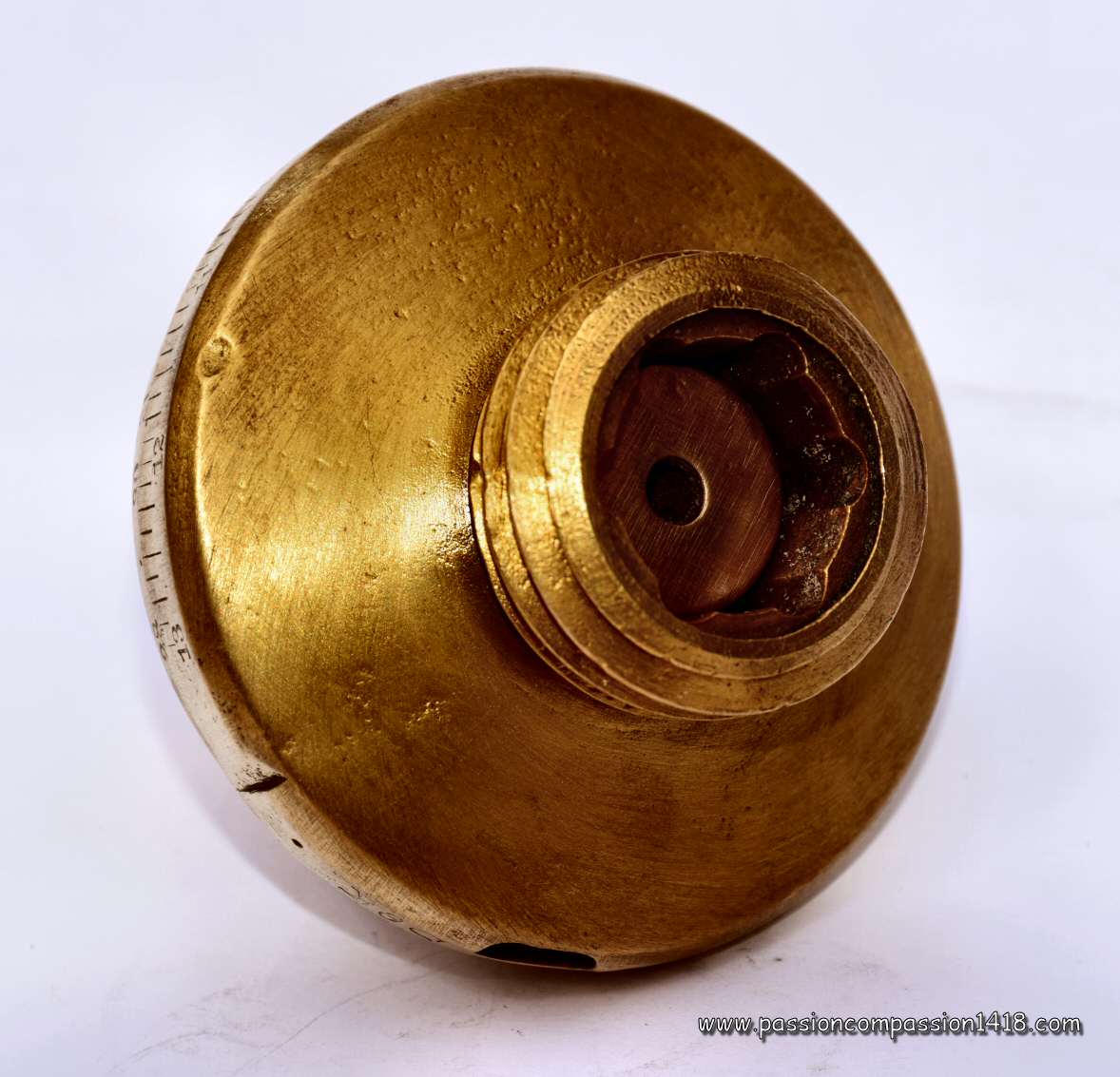
Fuze Dopp Z 92. View from below, with the 6 circular holes for the time system, and central hole (on the tail) for the percussion function |
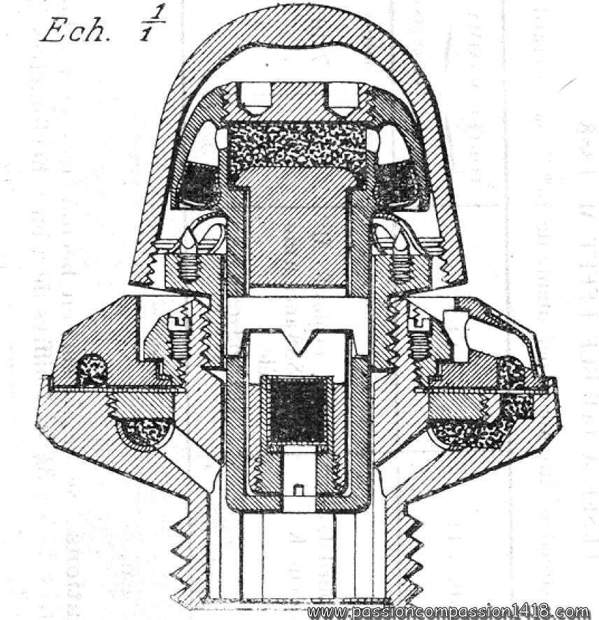
Fuze Dopp Z 92. Wartime scheme |
|
Return at the top of the page |
||
Dopp Z 92 nF fuze |
||
 |
The reason why this new version of the classical Dopp Z 92 fuze is far from being evident, since the inner devices - graze arming system and percussion system - of this two discs time and percussion fuze Dopp Z92 nF ('n.F.' = neue Form - nuw shape) look identical, as seen on the wartime schemes. It was also equipped with a two rods safety pin blocking the graze safety system.
The only noticeable differences were in the external shape, more round, and sometimes the material used that could be brass, but also aluminium. The Dopp Z 92 nF was graduated from 2 to 41 seconds on its lower ring, like the elongated combustion time Dopp Z 92 lg Brlg fuze version, justifying the slightly modified Dopp Z92 lg Brlg nF name that was sometimes used as well. A version without safety pin was developped with the Dopp Z92 nF o.Vorst. fuze This fuze was mounted on the shrapnel shells, incendiary shells and high explosive shells of the :
|
|
Fuze Dopp Z 92 nF |
||
 |
 |
|
Fuze Dopp Z 92 nF in brass. Indications 'Dopp Z 92 nF - SSWN17 - h - sw265' |
Fuze Dopp Z 92 nF. Another specimen more complete. Indications 'Dopp Z 92 nF - 23' |
|
 |
||
Fuze Dopp Z 92 nF in brass, dismantled. Zoom on the rotating discs grooves' |
||
 |
 |
|
Fuze Dopp Z 92 nF : hole for escape of the combustion gases from the fusing black powder |
Fuze Dopp Z 92 nF : anoyher specimen, markings 'Dopp Z 92 nF - SSWN18 - SHE177 -13' |
|
 |
||
Fuze Dopp Z 92 nF, dismantled disks. Picture courtesy J Faulkner |
||
 |
 |
|
Fuze Dopp Z 92 nF in aluminium and brass. Evidently, the brass parts are more resistant to time aggression than the aluminium ones. Zoom on the brass to. Identification 'c' |
Fuze Dopp Z 92 nF. Wartime scheme |
|
Return at the top of the page |
||
Dopp Z 96 and Dopp Z 96 n/A fuze |
||
 |
The two discs time and percussion fuze Dopp Z 96 was a device specifically designed for the 7.7cm FK96 n/A fieldgun, standard light gun of the IInd Reich field artillery in 1914.
In its initial version graduated from 0 to 50 hundreds of metres, this fuze was an other variation of the classical two discs time and percussion system of the Dopp Z 92 fuze, with the same classical graze action arming system secured by a two rods safety pin and based on a massive mobile pellet and a static percussion pin protected by a tulip spring, and the tail graze percussion system based on a cylindrical graze pellet bearing a starter and a static percussion pin transverse bridge. The time system, ignited by the graze action arming system, was a two discs one. The upper disc, with the graduation engraved, was static and attached to the fuze body. Despite these similarities, the will to develop a lightened fuze specifically adapted to the shells of the light fieldgun was obvious, illustrated both by the inner components dimensions that were reduced, and by the choice of the materials, only steel and aluminium instead of the heavier brass, long before the war economical restrictions imposed this choice on other German fuzes. Later a new version Dopp Z 96 nA ('nA' = neue Art - new design') was graduated from 0 to 53.5 hundreds of metres, then in subsequent versions from 0 to 71.5, 0 to 65 and 0 to 70 hundreds of metres. Externally very similar to the earlier version but for the graduations, in included indeed a brand new graze action arming system, this time composed of a lighter mobile graze pellet separated from the static percussion pin by a spring instead of the usual 'tulip'. This version did not include any safety pin. That fuze in all its versions was used in big quantities? It was mounted at the beginning of the war on the shrapnel shells and high explosive shells of the :
The Dopp Z 96 fuzes can be observed frequently nowadays in museums or on former battlefields, but in this latter case the surviving bodies are often badly corrded, because of the not so noble nature of its components. |
|
fuze Dopp Z 96 n/A. |
||
|
 |
|
fuze Dopp Z 96 n/A. Only visible markings : Dopp Z 96 n/A, graduated up to 6500 metres. Observed in Champagne |
fuze Dopp Z 96 n/A. This one has been transformed into an inker (trench art). Graduated up to 72.5, markings 'Dopp Z 96 n/A - Kr.484 - 5' |
|
 |
 |
|
fuze Dopp Z 96 n/A. Rear view, showing the groove (gunpowder circular line) of the rotating disc (the static disc is missing) |
fuze Dopp Z 96 n/A. Bad condition specimen, and the poor remainings of another piece in terrible condition ! |
|
 |
 |
|
fuze Dopp Z 96. Another specimen, in better condition, graduated up to 5000 m. |
fuze Dopp Z 96. The brown-reddish painting is the original one... |
|
 |
 |
|
fuze Dopp Z 96 n/A. Rear view, with rear charge igniting holes |
fuze Dopp Z 96 n/A. Wartime scheme |
|
Return at the top of the page |
||
Dopp Z 98 fuze. |
||
 |
Little is known about the Dopp Z 98 fuze that was developped exclusively for use with the howitzer shell '10cm FeldHaubitze schrapnell 1898', and was very likely an evolution of the Dopp Z 92 fuze.
Graduated from 2 to 56 hectometers, and equipped with a tail detonator like the other 'Dopp' zunders, it has been abandoned before the war at the same time than the shell it has been designed for. However, some fuzes of this type can still be observed nowadays on battlefield (including on the former eastern front), so it is probable that some old stocks of these ammunitions were used anyway during WW1. That fuze was used with the shrapnell shells of the :
|
|
Fuze Dopp Z 98. |
||
 |
 |
|
Fuze Dopp Z 98. Markings 'Dopp Z 98 Sp', observed on the former eastern front |
Fuze Dopp Z 98. Top view |
|
 |
 |
|
Fuze Dopp Z 98. Bottom view on the tail detonator. |
Fuze Dopp Z 98. 3D picture courtesy Pascal Casanova |
|
Return at the top of the page |
||
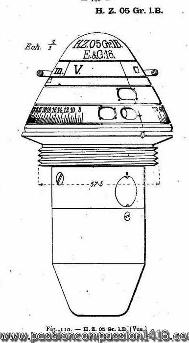
HZ 05, HZ 05 Gr and HZ 05 Schr fuze |
||
 |
Just like many other nations before the WW1, the German Army developped for its field artillery different 'universal shells' that could behave as high explosive or shrapnel shells. Complex and never as good as the pure high explosive or shrapnel shells, this ammunition had another disadvantage to require the use of sophisticated fuzes able to activate the different functions of the shell. The HZ 05 fuze was therefore designed for the universal shells of the light field howitzers 10cm lFH 98/04. Later, the KZ 11 fuze will follow for the universal shells of the 7.7cm FK96 n/A light field guns.
Technically, the original HZ 05 fuze was a quadruple effect fuze :
It was using technologies introduced by earlier fuzes :
Another interesting specificity was given by the fact the exploder could be burst also by the time system by a channel linked to the lower time disc through a small delay, so that it would explode just after the fuze is ejected from the shell behaving in shrapnel mode. The relative lack of efficiency of the universal shells induced their progressive removal from the Army (obsolete in July 1916) as well as their specific fuze, but the design of the HZ05 was later simplified in order to give birth to two derivated versions intensively used during WW1 :
|
|
fuze HZ05. |
||
 |
 |
|
Early HZ05 fuze. Markings 'HZ 05 - Dr 15' say that this fuze has been produced in Dresden in 1915. Collection AZE AZEE |
Early HZ05 fuze. Markings 'nur G / Bz'. When this position was selected, the fuze was programmed to function on a high explosive time mode. Collection AZE AZEE |
|
 |
 |
|
Early HZ05 fuze. Markings 'HZ 05 - Sb 15'. Picture courtesy Matt Reef |
Early HZ05 fuze. Rear view showing the different tail apertures of this sophisticated fuze that had to be associated with a detonator. Picture courtesy Matt Reef |
|
 |
 |
|
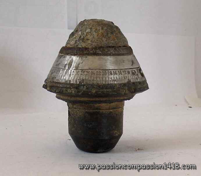
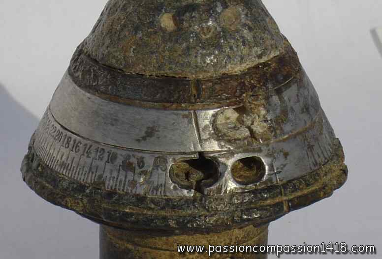
HZ05 Gr fuze. markings 'H.Z.05.Gr. - Sp15'. Nice specimen set for a percussion function. |
HZ05 Gr LB fuze. This trench art is made from the 'LB' variant of this fuze, with a graduation extended up to 70 hectometres. Markings 'H.Z.05.Gr.LB - Sp17M' |
|
 |
||
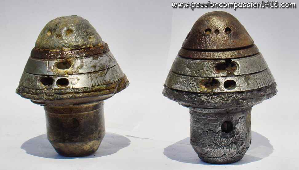
HZ05 Gr fuze. Two similar specimens, but one of them have lost its aluminium parts due to corrosion. |
||
 |
||
HZ05 Gr fuze. Wartime scheme of the initial HZ05 fuze, for universal shell. |
||
 |
 |
|
HZ05 Gr fuze. Lower view, showing the classical bottom holes of the detonator, the two percussion systems, and the arming stem. |
HZ05 Gr fuze. Wartime scheme. |
|
 |
 |
|
HZ05 Schr fuze. Nice specimen, made of different materials, observed in Verdun |
HZ05 Schr fuze. No visible markings (graduations excepted). This fuze has been shot on the setting 'roman cross' = impact percussion for shrapnel shell. |
|
 |
||
HZ05 Schr fuze. Two specimens with different materials. The one with the preserved steel head is marked 'HZ05 Sb16' on it |
||
 |
 |
|
HZ05 Schr fuze. View from below, showing the window communicating the flame to the central canal in the direction of the back gunpowder room of the shrapnel shell |
HZ05 Schr fuze. A destroyed specimen, note the circular lines of the static disc on which the rotating disc was revolving, and in the center the percussion pin of the arming system. |
|
 |
 |
|
HZ05 Schr fuze. Wartime scheme, showing the safety pin of the concutor |
HZ05 Schr fuze. Wartime scheme |
|
Return at the top of the page |
||
KZ 11 and KZ 11 Gr fuze |
||
 |
Just as the HZ 05 fuze that had been introduced for similar ammunitions of the light field howitzers, the use of the German 'universal shells' of the light field gun 7.7cm FK96 n/A needed the design of special fuzes able to command the different behaviors of this polyvalent shell (with lead balls and rear charge for shrapnel behavior, reinforced wall thickness and TNT filling between the balls for a high explosive behavior).
For this purpose appears in 1911 the 'KZ 11' fuze, designed in light materials just like the Dopp Z 96 fuze of the shrapnel shells from the same fieldgun, but much more sophisticated. It was a triple effect fuze :
The KZ 11 introduces a brand new system integrating the graze action arming system and the percussion system safety functions, that will be used from then in numerous other fuzes like the LKZ 11, KZ 14, HZ 14 and Gr Z 14 : It includes two parallel vertical cylindric rooms located under the fuze cap. One of them contains the graze action arming system, with a light mobile pellet bearing the primer separated at rest from a static percussion pin by a simple spring, without safety pin. At the shot departure, the mobile pellet compressed the spring under the momentum action, and the resulting flame is communicated to both the gunpowder ring of the first time ring of the time system, and to the second cylinder. The safety device of the percussion system is located in this second cylinder : a big compressed gunpowder pellet forbids the movement of a vertical stem blocking the percussion system located inside the fuze tail. When the flame communicated by the time pellet system burns this gunpowder pellet, the stem is liberated and pushed up by a previously compressed spring. The gasses emitted by this consumption are ejected outside the fuze by a gaz escape. The time system was a two discs one : the upper, static, was graduated from 2 to 50 hundreds of metres, and the lower, mobile, with the setup rule and on each side a correction system graduation from '-8' ('L') to '+8' ('K'). The flame emitted by the lower disc at the end of the combustion time could be directed by a valve either to the exploder for high explosive behavior or the shell (position 'G' - 'Granate'), or to a circular gunpowder track around the tail and pierced with 6 windows communicating with the shell rear charge for a shrapnel behavior of the shell (position 'S' - 'Shrapnel'). It must be noted that a 'KZ 11 lB' version with a combustion time elongated to 70 hundreds of metres existed too. The percussion system located in the fuze base included a mobile pellet bearing the primer (blocked at rest by the stem commanded by the arming system), and a percussion pin protected by a safety spring. The high explosive behavior of the shell required the association of the KZ 11 with a 23 gr picric acid exploder. It was mounted on the universal shells of the :
|
|
Fuze KZ 11. |
||
 |
 |
|
KZ 11 fuze. Nice specimen in good condition |
KZ 11 fuze. Another view of the same specimen |
|
 |
 |
|
KZ 11 fuze. Zoom on the corrector scale |
KZ 11 fuze. Zoom on the flame selector : Shrapnell for the rear charge, Granate for the central detonation |
|
 |
||
KZ 11 fuze. Most of the time, this fuze is only found in really damaged condition |
||
 |
 |
|
KZ 11 fuze. specimen in bad condition observed in Verdun |
KZ 11 fuze. Wartime scheme |
|
 |
 |
|
KZ 11 fuze. Nice specimen with the exploder still present. The corrector range markings have disappeared. Collection Luc MALCHAIR |
KZ 11 fuze. fuze base view. Pictures courtesy Luc MALCHAIR |
|
 |
||
KZ 11 fuze. Dismantled specimen, view from above. Pictures courtesy Luc MALCHAIR |
||
Return at the top of the page |
||
LKZ 11 Gr fuze |
||
 |
Externally, the LKZ 11 Gr fuze looks like a simple aerodynamic improvement of the KZ 11 Gr fuze (version of the KZ 11 fuze dedicated to the high explosive shells whose time or percussion systems flame is directly communicated to the detonator), with an elongated cap allowing it to be mounted on streamlined shells. However, this fuze differs by some noticeable changes.
The graze action arming system and the time system was kept identical to the ones of the KZ 11 Gr. In the original model, the mobile upper disc was graduated from 4 to 72 hundreds of metres. Like the KZ 11, it was made of steel and aluminium, with sometimes some brass for the body, and zinc alloy for the ogival cap. The percussion system safety devices with blocking stem and safety spring had been replaced by a centrifugal system with two bolts with springs blocking the graze pellet and pulled back by the shell spin. Moreover, the exploder was equipped with an arming system with centrifugal lock, preventing the flame of the percussion primer or the one from the time system to communicate with the exploder explosive before an obturating lock rotates under the action of the centrifugal force. Associated with a 23 gr picric acid detonator, the LK Z 11 Gr was mounted on the high explosives shells of the :
Another version is also known :
|
|
LKZ 11 Gr fuze |
||
 |
 |
|
LKZ 11 Gr fuze. Nice condition specimen, observed in Champagne, and having been programmed in percussion mode (mark set on the cross). Late version graduated to 50. |
LKZ 11 Gr fuze. Side view with the groove dedicated to the fuze tightening on the shell |
|
 |
 |
|
LKZ 11 Gr fuze. Zoom on the marking still visible on the zinc alloy cap 'LKZ 11 Gr Zp' |
LKZ 11 Gr fuze. Zoom on the time system two escapes and on the marking 'kB' confirming this one is a late version with shortened combustion time ('kurze Brennlänge') |
|
 |
 |
|
LKZ 11 Gr fuze. lower view. Several inside mechanisms can be seen, the brass disc seems to be the base of the percussion system. |
LKZ 11 Gr fuze. Wartime scheme/font> |
|
 |
 |
|
LKZ 11 Gr fuze. Damaged model observed in Massiges. It is again a late version 'kB' graduated to 50. Markings 'LKZ 11 Gr DpZ1(?)' |
||
 |
||
LKZ 11 Gr fuze. 3D drawing by Pascal CASANOVA. This is an early model, graduated to 72 hundreds of metres. (see the 3D Fuzes specific section of this website for numerous examples of his great work) |
LKZ 11 Gr fuze. Cut at the level of the first disc |
|
Retour en haut de page |
||
Dopp Z 15 fuze |
||
 |
In 1915, a new triple effect fuze for the high explosive shells of the heavy artillery appeared, named Dopp Z 15. Its graze action arming system was the classic one based on based on a massive gunpowder pellet and a percussion pin protected by a tulip spring, gunpowder pellet blocking the percussion system by a stem and secured by a two rods safety pin. This system was inspired by the 'Dopp Z 92' fuze.
The two discs time system communicated the flame to the exploder primer. The mobile lower disc was graduated from 2 to 41 seconds. Its movements were blocked at shell departure by a needle activated by the shock momentum. The percussion system was made of two apparatus, one with delay and the other one without. The delayed device was secured by a centifugal bolt whose movements were made possible by the combustion of a gunpowder pellet triggered by the safety graze system. The delayed device was lateral and blocked by a mechanical system (stem and gear) commanded by a setting stud on the fuze head. Set on the 'm.V.' position, the setting stud deactivated the system without delay and the fuze acted with a delay. Set on the 'o.V.' position, both devices were activated, so the fuze acted without delay. The attached big 90 gr picric acid exploder was equipped with a safety system identical to the one of the Gr Z 04 fuze with an isolated detonating room (10 gr picric acid in the mobile charge). The Dopp Z 15 fuze was mounted on the high explosive shells, aiming shells or smoke shells of the :
Some specimens were marked 'Dopp Z 15 umg.' ('umg. = umgeändert - transformed), with no known reason. |
|
fuze Dopp Z 15. |
||
 |
 |
|
Dopp Z 15 fuze. Body made of brass, middle ring and upper screw in steel. markings : 'Dopp Z 15 - u.m.g. - m.V. - o.V.'. Found in the Somme |
Dopp Z 15 fuze. Another view with graduations from 0 to 41 seconds |
|
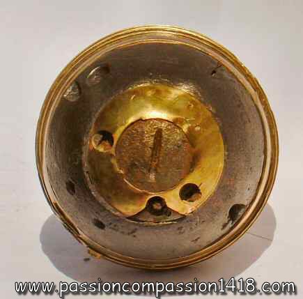 |
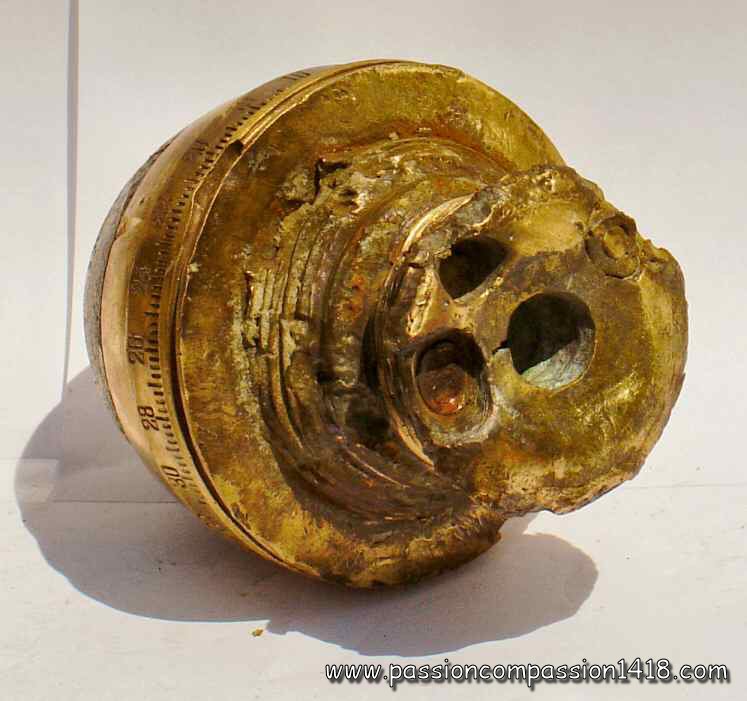 |
|
Dopp Z 15 fuze. Upper view |
Dopp Z 15 fuze. View from below showing the exits of both the percussion systems, the end of the stem of the arming system, and the one of the detonator |
|
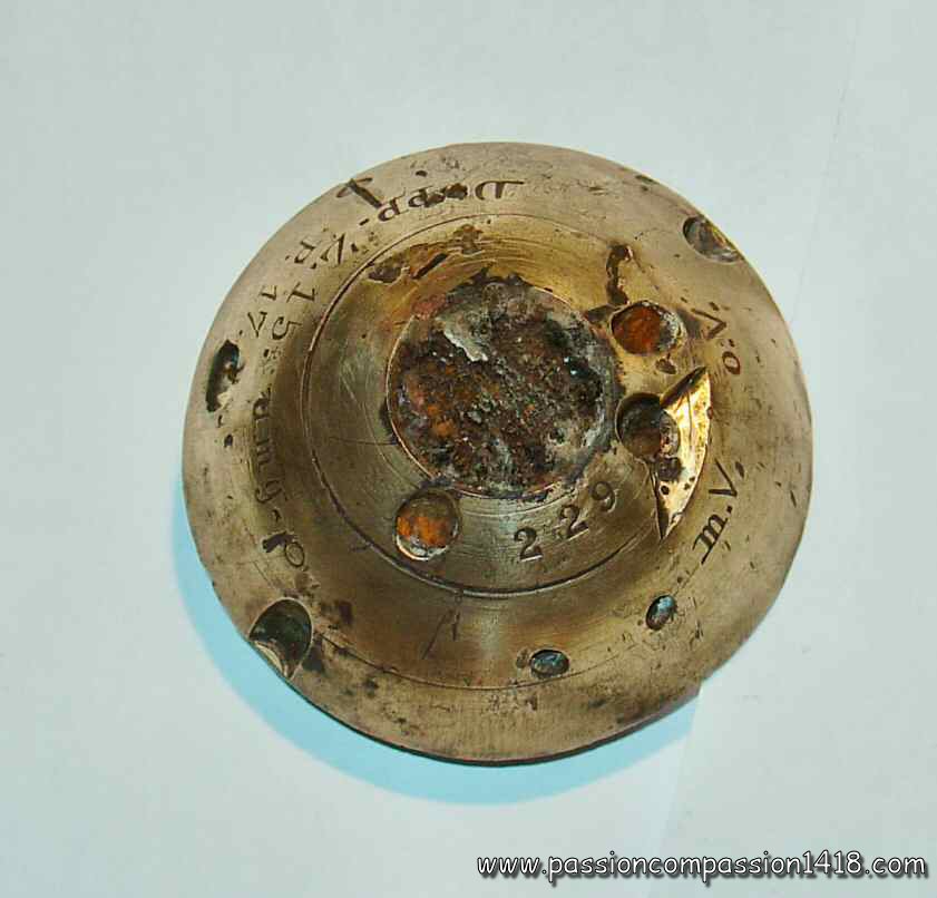 |
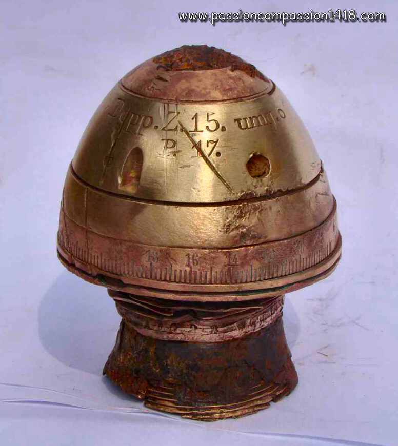 |
|
Dopp Z 15 fuze. Another specimen, more damaged but middle ring made of brass. Found in Ypres. markings : 'Dopp Z 15 - u.m.g. - o - P17 - o.V. - m.V. - 229' |
Dopp Z 15 fuze. Another full brass specimen, observed in Champagne. Markings 'Dopp Z 15 - u.m.g. - o - P17 - o.V. - m.V. - 187'. |
|
 |
 |
|
Dopp Z 15 fuze. Zoom on the delay selection system : o.V. = without delay; m.V. = with delay |
Dopp Z 15 fuze. Wartime scheme |
|
Return at the top of the page |
||
Dopp Z S/43 fuze |
||
 |
Although principally using high explosive shells rmed with percussion fuzes for its combat missions, the German Navy also had to equip with anti-personal ammunitions in order to destroy the enemies manning the ship decks or onshore defenses, or for anti-aircraft use. Therefore the Marine arsenals mnufactured time and percussion fuzes specifically designed for the long barrel marine tubes with long range end high initial acceleration.
This context is the reason of the apparition of the Dopp Z S/43 ('S/43' as '43 sekunden') time and percussion fuze. Modest in size and pretty sophisticated, it resisted well to the violent accelerations produced by the long Navy guns, and allowed remarkable long combustion times thanks to the use of a slow burning powder composition for the time tracks. It had a 50 mm diameter thread on its base, adapted to the standard of the marine shells. This fuze concussion system located into the fuze ogival head was based on a top mobile pellet bearing a primer and projected backwards onto a static percussion pin under the effect of the shock of departure. The safety of the concussion system was insured by the means of a to spring retaining the movements of the mobile pellet from the top, a thin soft metal plate retaining its movements from the above, and in some models a simple rod traversing safety pin. The concussion system ignition transmitted the flame to the combustion track start of the time system (through radial channel equipped with a small pyrotechnic delay to avoid prematures in the tube), and to a compressed gunpowder pellet located under the concutor percussion pin and blocking at rest the movements of the percussion system. The time system was composed of two discs, the upper being static and the lower being mobile and graduated from 1 to 43 seconds by 0.2 seconds steps. The percussion system was based on one of the classic german types with a static percussion pin located on a transverse bridge and a graze action pellet bearing the percussion primer and blocked at rest by a safety compressed gunpowder pellet. It did not have any safety spring in between the two pieces. At the end of the selected combustion time and/or at impact, the flame of the time system and/or tye percussion system was communicted to the rear gunpowder room, setting fire to the shell. When used with high explosive shells, this fuze was associted with a 'Gr. Zdlg C/98 m. 0.05 Sek. Verz.' detonator M 1898. The Navy time and percussion fuzes were also used with the shells of the Navy tubes adapted to the Army during the war as well as the ones of the flak, although keeping their Marine typical 50mm thread. The Dopp Z S/43 fuze mainly equipped the high explosive shells of the :
|
|
Dopp Z S/43 fuze. This model is a variant with a steel fuze head and intermediate disk, and a machined sides intermediate disc for a pure ogival fuze profile |
||
 |
 |
|
Dopp Z S/43 fuze. Top view. The steel head has been corroded and did not keep its markings, but still shows the two cavities designed to ease the screwing of the fuze into the shell body. |
Dopp Z S/43 fuze. View on the graduations from 1 to 43, the lower selection mark pointing on the cross symbol for a percussion behavior, and the several combustion gas escape vents |
|
 |
 |
|
Dopp Z S/43 fuze. Rear view on the empty gunpowder rear room and the primer pellet of the percussion system |
Dopp Z S/43 m. Vorst.fuze. War time scheme of the version with a safety pin |
|
 |
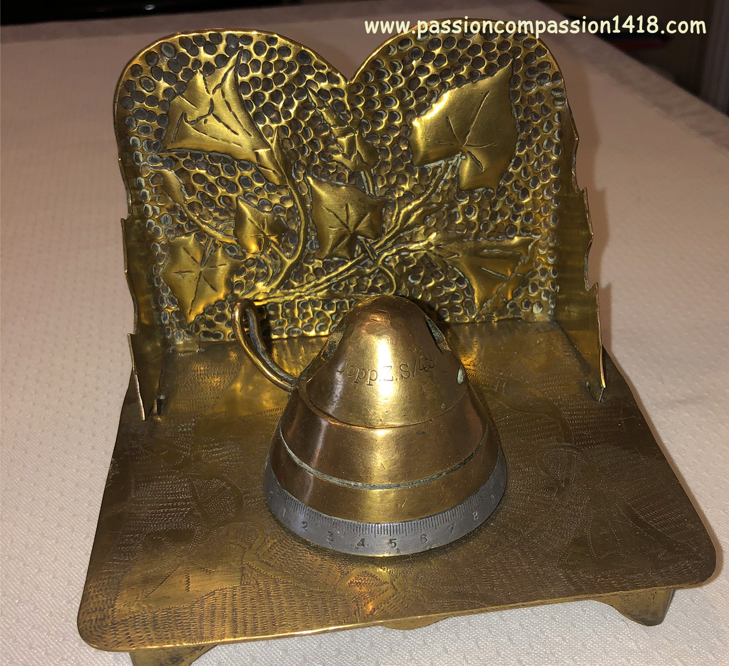 |
|
Dopp Z S/43 fuze. This cap is in brass |
Dopp Z S/43 fuze. Surprisingly, it is associated with a British N°80 fuze body in this trench art production |
|
Return to the top of the page |
||
Dopp Z S/26 fuze |
||
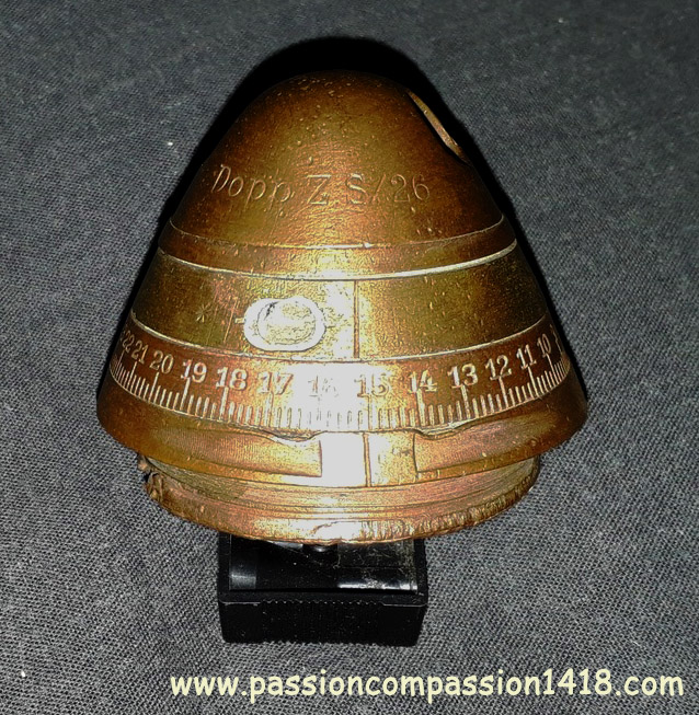 |
The ships of the German Navy were using 8.8cm L/30, L/35 and L/45 for the anti-torpedo defense, the attack of ship decks personnals, and later the anti-aircraft defense.
The time and persussion fuze Dopp Z S/26 ('S/26' for '26 sekunden') has been specifically created around 1916 to equip the shells of these weapons. Its inner organization was almost the same as the 'Dopp Z S/43' fuze, but for the use of a gunpowder with a classical combustion speed for the time track, and the presence of a safety spring in the percussion pyrotechnic mechanism, preventing during the flight an unwanted movement of the graze action pellet blocked before the shot by a safety compressed gunpowder pellet. Its mobile disc was engraved with 1 to 26 seconds graduations with 1/5th steps, and a cross for selecting the pure percussion behavior. This fuze, initially designed for the Navy and used as such, was also used for the anti-aircraft applications ('flak'). The Dopp Z S/26 mainly equipped the high explosive shells of the :
|
|
Dopp Z S/26 fuze. This item is entirely made in brass. |
||
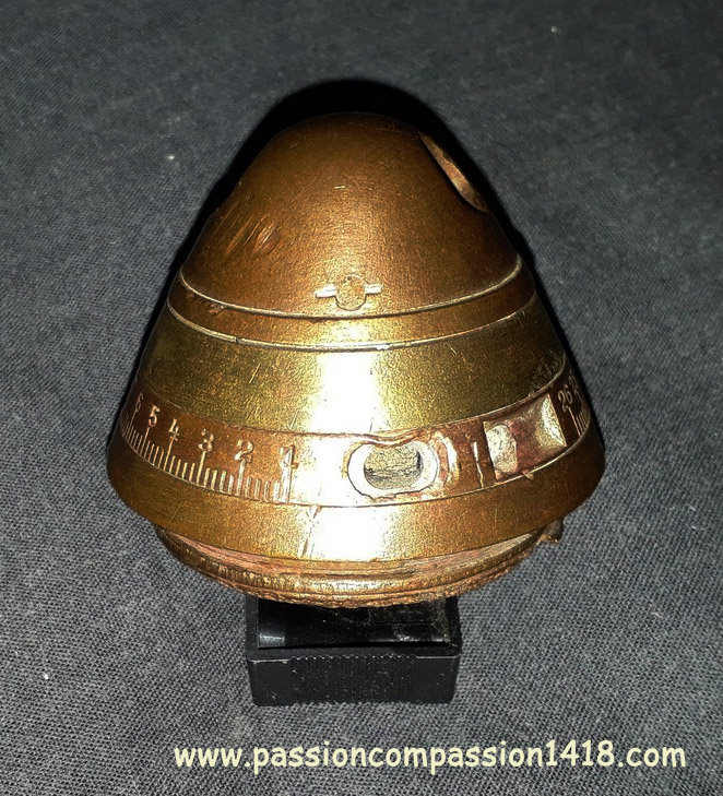 |
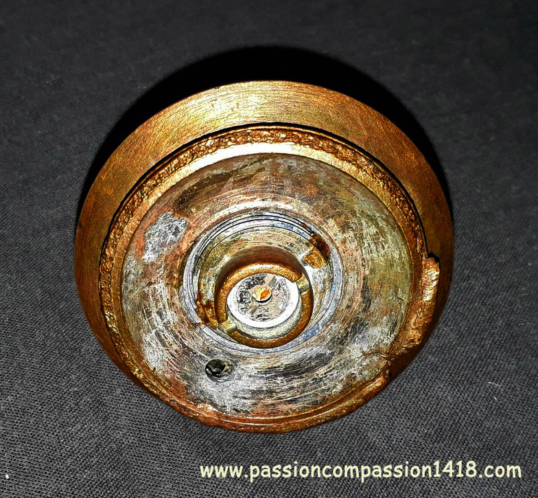 |
|
Dopp Z S/26 fuze. |
Dopp Z S/26 fuze. View from below |
|
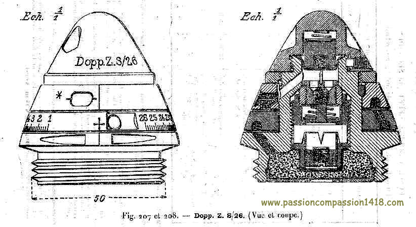 |
||
Dopp Z S/26 fuze. Wartime scheme |
||
Retour en haut de page |
||
Dopp Z 56 fuze |
||
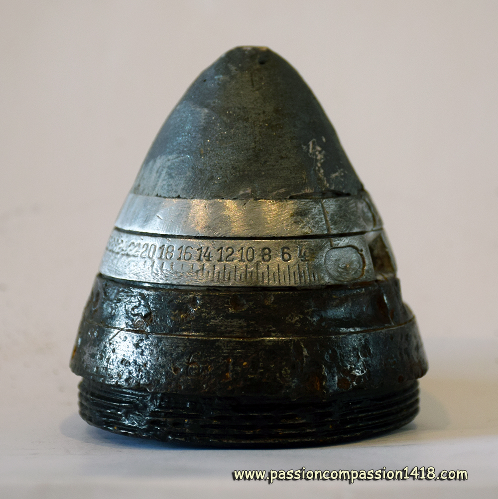 |
Several variants of time and percussion fuzes with different combustion times were adopted by the German Navy. Together with the 'Dopp Z S/26' and 'Dopp Z S/43' fuzes, one can also find the Dopp Z 56 fuze. The internal organisation of this fuze was very similar to the one of the other Marine fuzes.
Very little information can be found for it, for sure a clue indicating its use was not frequent. As it is a Krupp made fuze internal Krupp designation would be "Dopp.Z. 56 hm" but these Krupp designations are rarely seen in any documents. Some wartime allied intelligence documents are naming it "Dopp Z ? (56)" without any official identification marking, and interprete the 0 to 56 graduation marks as seconds. This is a mistake that has been demonstrated by one of this website's contribuor Stefan Wagner. The scale of the time ring is graduated in hectometers (numbers) and half hectometers (line) Hectometer scales can be easily distinguished from time scales. Time scales are constant/linear: The distance from one second to the next one the ring always equals, as the combustion speed of the gunpowder track is constant. Distance scales are logarithmic because the projectile slows down on it's travel. The first hectometers on the ring have a small distance the last hectometers have a much larger distance on the scale. The Dopp Z 56 fuze mainly equipped the high explosive shells of the :
|
|
Dopp Z 56 fuze. This item in incomplete : the head has been rebuilt and the first disc is missing. |
||
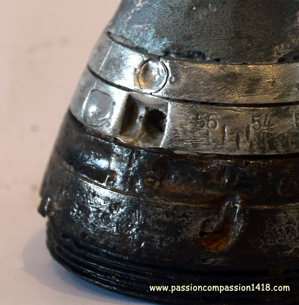 |
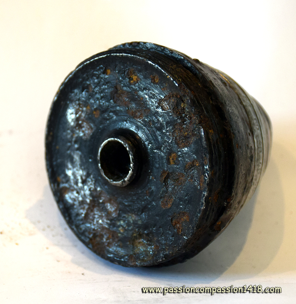 |
|
Dopp Z 56 fuze. View on the two discs, with the 56 hectometers maximum graduation. Notice both the fume vents are stil closed. |
Dopp Z 56 fuze. Rear view. |
|
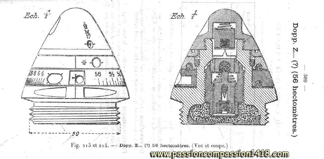 |
||
Dopp Z 56 fuze. Wartime scheme |
||
Return at the top of the page |
||
Fusée Dopp Z 16 |
||
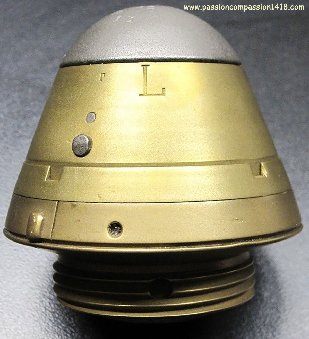 |
The first clockwork fuze appeared in Germany before the war, with the ‘Dopp Z O8’ fuze, which was fundamentally innovative in replacing the pyrotechnic fuzing device with a mechanism derived from clockwork mechanisms. This design made it possible to both
The Dopp Z O8, designed for the 10cm, 13cm, and 15cm caliber guns of the FussArtillerie, proved to be too fragile in its aluminum design to withstand the brutal forces exerted on its delicate mechanisms when the shot was fired. It was therefore little used, and the remaining stock was eventually used with parachute-equipped illumination bombs. To replace it, the ' Dopp Z16' fuze appeared, this time made of brass and steel, with more resistant internal mechanisms and a detonator tail similar to that of the ‘Dopp Z 92’ fuze. Like all clockwork fuzes of the time, it consisted of:
Without going into the particularly complex details of its design and operation, we can try to describe how it worked as follows: the clockwork mechanism was driven by a spiral spring (the “motor”) wound up in the factory. Released by a cocking mechanism at the start of the shot, it set in motion a series of two gear wheels and pinions (the “gear train”). The constant speed of rotation of this gear train was ensured by a balance wheel system (the ‘regulator’) driven by a toothed pinion driven by one of the gears (the ‘escapement’). This entire regulating mechanism gave the axis of rotation ('the barrel') located at the center of the mainspring a slow, constant, and precise speed of rotation. This barrel was directly connected to the trigger mechanism (or ‘release’ mechanism), which consisted of a key-like piece. This was released at the start of the shot by the removal of a lock activated by inertia, then turned under the effect of the slow rotation of the barrel. When its profile coincided with two notches in the brass body of the fuse, it was inserted into them by a spring, triggering the firing device and at the same time releasing the tail of the striker, which was then projected towards the primer, causing the rear detonator of the fuze to explode. The flight time — maximum 60 seconds — was set using a special key by rotating the movable head of the fuze, which brought the notches to a precise angle in relation to the resting position of the trigger key. The assembly included several safety mechanisms. Needless to say, these fuzes with clockwork mechanisms were much more complicated and expensive to produce. The ‘Dopp Z16 o. Az.’ (ohne Aufschlagzundung - without percussion mechanism) version was designed for anti-aircraft guns. The Dopp Z 56 double-effect fuze was mainly used in the shrapnel shells of:
The single-effect Dopp Z 56 o.Az. fuse was used in the shrapnel shells of:
|
|
Dopp Z 16 fuze. Very nice example seen on an auction site |
||
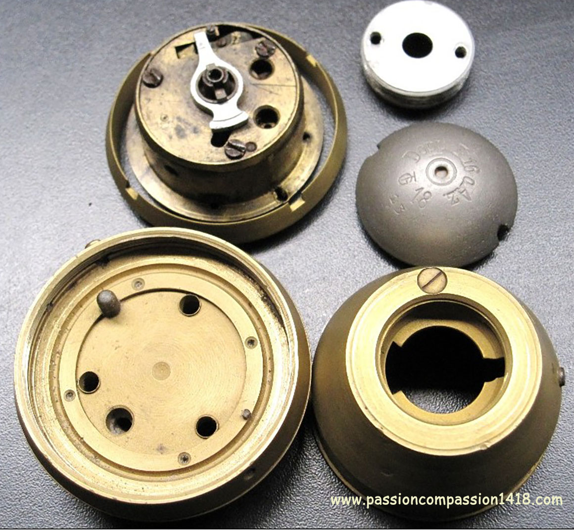 |
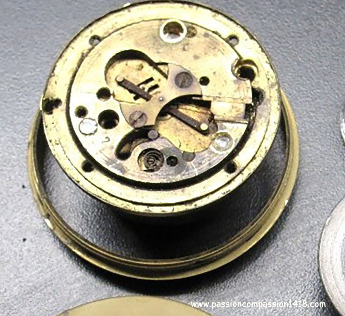 |
|
Dopp Z 16 fuze. This model, marked ‘Dopp Z 16 o.Az. TG18’, can be dismantled. See here for the release key and notches. |
Dopp Z 16 fuze. With the internal block turned over, the balance wheel is clearly visible: a brass blade with weights at each end. |
|
 |
 |
|
Dopp Z 16 fuze. The key is aligned with the notches, triggering is permitted. |
Dopp Z 16 fuze. Close-up of the notches on this specimen hollowed out by a combatant. |
|
 |
 |
|
Dopp Z 16 fuze. This specimen was hollowed out by a veteran to make a souvenir. The discs and threading are missing. See the letter T above the lugs, which have been filed down. |
Dopp Z 16 fuze. Markings 'Dopp Z 16 - 29' on the top steel cap. |
|
 |
 |
|
Dopp Z 16 fuze. Wartime scheme |
Dopp Z 16 fuze. Wartime schematic to help understand how this fuze was working. |
|
Retour en haut de page |
||
Bd Z 06 fuze |
||
 |
The Bd Z 06 'Boden Zunder' - 'bottom fuze' was a device that was screwed on the bottom of heavy explosive shells, whose nose cone was solid and massive in order to improve the penetrating properties of the projectile.
Entirely made of brass, this fuze had two percussion systems aligned vertically in the same central axial channel : From the fuze tail to the fuze base, this pyrotechnic column was composed of
A fuze base gaz escape also existed linked to all the internal pyrotechnic devices, closed at rest by a compressed gunpowder pellet burnt by the gun departure hot gasses. In the case of a non-delayed behavior, the non-delayed system mobile graze pellet carrying the pin was liberated by positionning the bottom selector on the 'o/V' mark (allowing the flame of the diaphragm arming system to burn a gunpowder pellet blocking a lock). At the arrival on the target, the top (delayed) percussion system was triggered by having the mobile graze pellet primer hitting the static percussion pin, while the rear (non-delayed) mobile graze pellet percussion pin went forward to hit the rear primer. This latter instantaneously ignited the detonator charge. In the case of a delayed function, the non-delayed system mobile graze pellet carrying the pin was kept static by positionning the bottom selector on the 'm/V' (preventing the lock gunpowder to burn). At the arrival on the target, only the top (delayed) percussion system was triggered by having the mobile graze pellet primer hitting the static percussion pin. This set fire to the delay channel, 0.3 seconds before bursting the detonator. This fuze also integrated a detonator safety system. The detonator located in the mobile graze pellet was positionned at rest in an isolated detonation room, not communicating with the fuze outside. On the contrary, when the mobile graze pellet was projected onwards, this positioned the detonator in front of windows communicating with the exploder (unknown charge) in wich the fuze tail was inserted. The Bd Z 06 fuze was used with the high explosive shells of the :
|
|
BdZ06 fuze. |
||
 |
 |
|
BdZ06 fuze. Face view. Some cracks from the explosion |
BdZ06 fuze. The part with the detonator has been sawed. The 6 holes in the lateral disc allowed the gun gasses pressure to press on a diaphragm that would trigger a primer burning the gunpowder pellets of the percussion system safety bolts. |
|
 |
||
BdZ06 fuze. Left item markings : 'Bd.Z.06 - Sp.10 - C5671 - M/V 0,3'' - o/V. Right item markings : 'Bd.Z.06 - Sp.10 - B9171 - M/V 0,3'' - o/V. |
||
 |
 |
|
BdZ06 fuze. The sawed surface shows the central percussion system pellet in the middle |
||
 |
||
BdZ06 fuze. Wartime scheme. See the two percussion systems aligned in the fuze axis |
BdZ06 fuze. Wartime scheme |
|
 |
 |
|
BdZ06 fuze. The two holes in the thread give access to the gunpowder pellets bolts of the percussion system. |
BdZ06 fuze. Other item bottom view. The tail has been torn by the explosion, showing remnants of the central rod. |
|
Return at the top of the page |
||
Bd Z 10 fuze |
||
 |
Although externally pretty similar to the Bd Z 06 fuze from 1906, the 1910 Bd Z 10 fuze was an complete re-design of the internals. In the new fuze, the complex twin percussion apparels systems has been replaced by a single non delayed percussion system linked to the detonator via three selectable channels for a non delay, small delay or long delay behavior)
The massive percussion system, parallel to the fuze axis, had a static percussion pin attached to the fuze bottom, and a massive mobile graze pellet carrying a primer, whose forward movements were made easier by 8 steel balls guiding the pellet base tail. This percussion system was secured at rest by a compressed spring lateral bolt hold by a gunpowder pellet. This arming system was the same as the one of the Bd Z 06, activated by the gun gasses pressure through 6 holes in the fuze base onto a diaphragm, whose deformation projected a pin to a small primer. Like in the Bd Z 06 too, a fuze base gaz escape also existed linked to all the internal pyrotechnic devices, closed at rest by a compressed gunpowder pellet burnt by the gun departure hot gasses. The flame created by the percussion system was transferred to the detonator via three channels, a long delay channel always open, a small delay and a no delay ones whose opening was selectable by rotation the fuze base delay selector :
The Bd Z 10 fuze could be associated with two sizes of exploders : 100 gr or 25 gr picric acid. When assembled with a big 100 gr picric acid exploder it was often marked lg Bd Z 10 ('lg' = 'lang', refferring to the long exploder). It was then used with the high explosive shells of :
|
|
fuze BdZ10 Sp16. |
||
 |
 |
|
fuze BdZ10 Sp16. Bought to a collector. Markings 'kzBdZ10 Sp16 - 0.7659 - (asterisc) - 0/V - 1/V - 2/V'. Set for a non-delayed function |
fuze BdZ10 Sp16. Observed in Massiges. Markings 'kzBdZ10 Sp15 - S.5252 - 0/V - 1/V - 2/V'. Set for a non-delayed function |
|
 |
 |
|
fuze BdZ10 Sp16. The base disappeared during the explosion |
||
 |
||
fuze BdZ10 Sp16. Wartime scheme |
fuze BdZ10 Sp16. 'kz' version wartime scheme |
|
 |
 |
|
fuze BdZ10 Sp16. Bits still present on a 210 mm shell bottom observed in Verdun |
fuze BdZ10 Sp16. Detail of the complex inner mechanism, destroyed by the explosion. |
|
Return at the top of the page |
||
ZsWM fuze |
||
 |
Germany started the Great War with an aresenal including 115 middle trench mortars (17cm mMW) et 44 heavy trench mortars (25cm sMW), initially designed for siege action against fortresses that had been passed around by invasion troops, but quickly very useful in the positions war that settles from the end of 1914..
The first projectiles from the 25cm sMW a/A heavy minenwerfers were lauched against some of the Liège fortified position fortresses, with devastating results. The high explosive shells of this kind of weapon needed specific fuzes taking into account the small initial speeds (less than 100 m/s), and the uncertain landing conditions (on the shell top, base or side). Made in brasse (and sometimes with an aluminium head), the impressive 'Z.s.W.M.' - 'zünder für Schwerer Wurf-Minen' ('Fuze for heavy mine launchers') fuze was equipped with a graze action percussion system that would trigger whenever the shell felt on its nose or on its base, and a time system designed to explode the shell after some seconds if the percussion system had failed. The ZsWM fuze integrated :
A steel plate cap was protecting the top plug and the arming system safety pin during transportation. This fuze was associated with a small exploder (unknown picric acid quantity). The heavy and probably expensive ZsWM fuze was replaced by the ZsumWM fuze in 1915. In, 1914, the ZsWM fuze was mounted on high explosive shells and gaz shells of the :
|
|
ZsWM fuze |
||
 |
||
Two ZsWM fuzes observed in Champagne. |
||
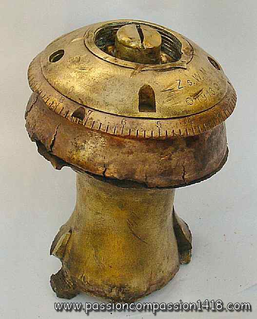 |
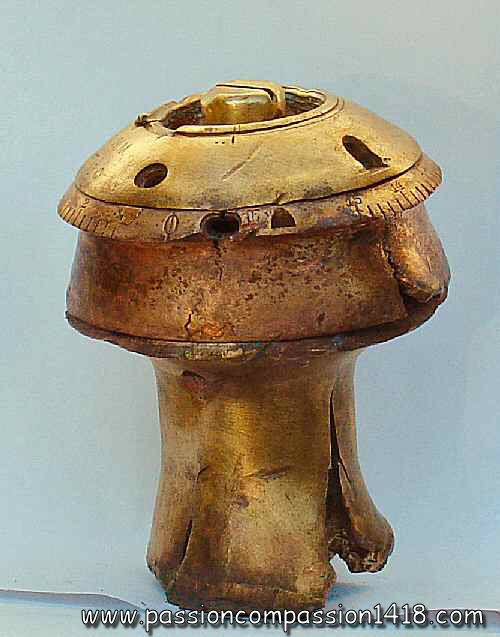 |
|
fuze ZsWM. Observed in Champagne |
fuze ZsWM. The lower fixed disc, with the thread, has disappeared during the mine explosion |
|
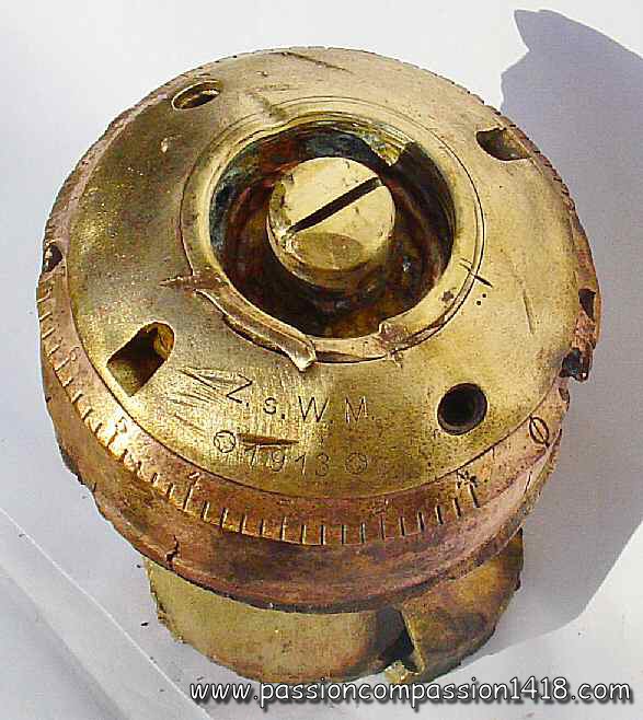 |
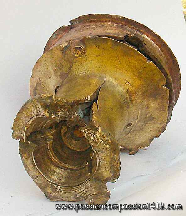 |
|
fuze ZsWM. Markings 'Z.s.W.M. - (losange in circle) - 1913 - (losange in circle)' |
fuze ZsWM. The lower part has exploded, showing the symetrical double starter-bearer |
|
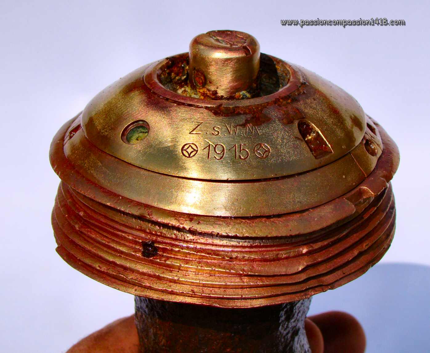 |
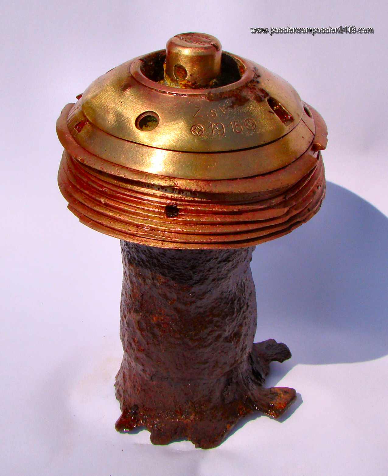 |
|
fuze ZsWM. Markings 'Z.s.W.M. - (losange in circle) - 1915 - (losange in circle)' |
fuze ZsWM. This specimen still has the detonator steel gaine around its tail. |
|
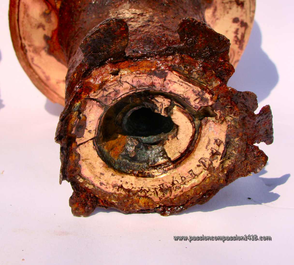 |
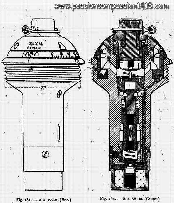 |
|
fuze ZsWM. View from below |
fuze ZsWM. Wartime scheme |
|
Return at the top of the page |
||
ZmWM and ZsumWM fuze |
||
 |
Since 1914, the German Army pionneers were given 175mm middle minenwerfers and 245mm heavy minenwerfers. A specific fuze was existing for each of the two models.
The 'ZmWM' fuze - 'zünder für mitteler Wurf-Minen' ('fuze for middle mine launchers') was the device dedicated to the 17cm mines. Realized in brass, it was based on :
After 1915, the ZmWM fuze was adopted also for the heavy minenwerfers instead of the big ZsWM fuze, and was renamed 'ZsumWM' - 'zünder für schwerer und mitteler Wurf-Minen' ('fuze for heavy and middle mine launchers'). It was mounted on the projectiles of the :
|
|
Fuze ZsumWM |
||
 |
||
fusée ZsumWM observed in Champagne. relay-charge dismantled, markings 'ZsumWM - Rh.M.F. 1917' |
||
 |
 |
|
Fuze ZsumWM. See the different holes, and the graduations with the roman cross for a percussion function. |
||
 |
||
Fuze ZsumWM observed in Champagne, with its attached relay charge and the safety pin still in place. |
Fuze ZsumWM. Set for an explosion after 14.8 seconds. |
|
 |
||
Fuze ZsumWM. Different materials (steel and brass) used for the head. Left fuze markings 'J 1916 J - Z.s.u.m.W.M. - 73'; right fuze 'Rh.M.M.1915 - P8826' |
||
 |
 |
|
Fuze ZsumWM. The upper parts, in aluminium alloy, are highly corroded. The 'fest' screw on the tail seems to be a variant. No markings visible |
Fuze ZmWM. Those earlier fuze were dedicated to the middle size minenwerfer. Markings 'Z.m.W.M. - AEG 1915 - F1639' |
|
 |
 |
|
Fuze ZsumWM. Zoom on the percussion function cross |
Fuze ZsumWM. Fuze ZsumWM bought in a flee market. See the ring with the safety pin. Markings '... u.m.W.... - 102' |
|
 |
 |
|
Fuze ZsumWM bought in a flee market. Detail of safety jaws of the percussion system |
Fuze ZsumWM. Wartime scheme |
|
 |
||
Fuze ZsumWM. Dismantled time system |
||
Return at the top of the page |
||
lWMZdr fuze |
||
 |
The first light minenwerfers 7.6cm lMW are not yet distributed to the pionneer units of the German Army when the fight begins in August 1914, but this weapon will quickly be more and more abundant, and distributed to the infantry units. Just like the middle and heavy minenwerfers, a specific fuze had to be developped to take into account the low initial velocity of the shells and its uncertian orientation when landing on the ground. The 'l.W.M. Zdr.' - 'Leichte Wurf-Minen zünder' fuze name specifies its exclusive use with the 7.58cm light mortar bombs :
The name of that fuze, 'l.W.M. Zdr.' - 'Leichte Wurf-Minen zünder', specified its exclusive use with the bombs of the 77 mm light minenwerfers :
|
|
Fuze IWMZdr |
||
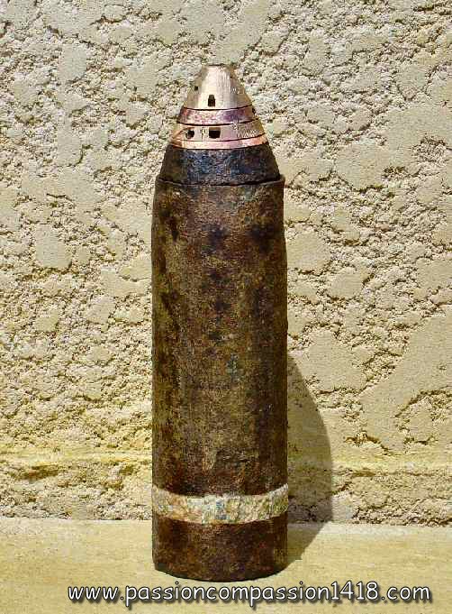 |
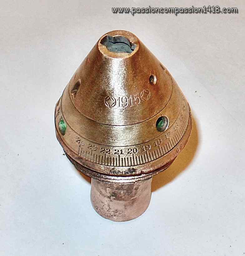 |
|
fuze IWMZdr. Found in Champagne - mounted on a 77 mm MinenWerfer Shell. Markings 'I.W.M.Zdr - losange - 1915 - losange'. |
fuze IWMZdr. View from above, with the head to hole for assembly of the flame-hiding cap for night shots. Markings 'I.W.M.Zdr - losange - 1915 - losange'. |
|
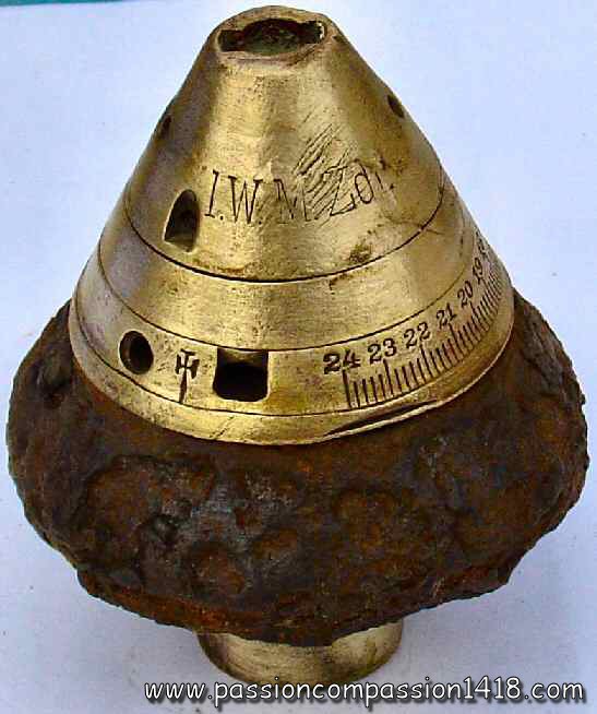 |
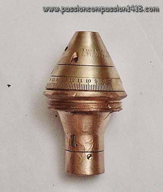 |
|
fuze IWMZdr. Note the different windows, and the roman cross for an impact percussion function. Markings 'I.W.M.Zdr - losange - 1915 - losange'. |
fuze IWMZdr. That piece is engraved with the markings 'IWMZdr - (rhombus)1915(rhombus)' seeming to indicate a 'MaschinenFabriek' (private society) manufacturing |
|
 |
 |
|
fuze IWMZdr. View from below showing the window communicating the flame to the detonator (missing) |
fuze IWMZdr. Wartime scheme |
|
Return at the top of the page |
||
lWMZdr2 fuze |
||
 |
The lWMZdr2 fuze was a slight modification of the lWM Zdr fuze, still dedicated to light trenchmortars shells.
The only modifications were :
These modifications were only internal and are practically not visible outside, but for the fuze marking that shows lWM Zdr 2 and the twin rods safety pin holes instead of one hole for the single rod system of the previous model. There was a variant of that fuze, introduced in 1917, with a threaded hollow tube inserted at the top of the fuze instead of the usual hole, still for the assembly of a flame-hiding cap for night time shots. Some pieces of the models from 1917 (time rings) were gradually made in aluminium instead of brass. |
|
fuze IWMZdr2. |
||
 |
 |
|
IWMZdr2 fuze. Markings 'Snake shape - IWMZdr2 - K - S - 1916 - P', with its relay charge tail. |
IWMZdr2 - 1917 variant. Marings 'IWMZdr2 - BR 1917 BR', with its relay charge tail and the safety pin. |
|
 |
||
2 fuzes IWMZdr2 at the right side of one IWMZdr. No noticeable external differences. Markings identical for both the right side fuzes : 'Serpentine - L.W.M.Zdr.2 - losange - 1916 - losange' |
||
 |
 |
|
fuze IWMZdr2. Disassembly of the time discs (picture on Delcampe auction) |
fuze IWMZdr2. Wartime scheme |
|
 |
 |
|
fuze IWMZdr2. The 1917 variant with the threaded tube at the top. Pictures courtesy Luc MALCHAIR |
fuze IWMZdr2. Wartime scheme of the 1917 variant |
|
 |
 |
|
fuze IWMZdr2. 1917 variant opened for access to the percussion system room. Pictures courtesy Luc MALCHAIR |
fuze IWMZdr2. 1917 variant rear view. Pictures courtesy Luc MALCHAIR |
|
 |
 |
|
fusée IWMZdr2. This fuze is equipped with its flame hider cap |
fusée IWMZdr2. When removed and turned upside-down, one can see the shape inside that can be iserted and locked inside thehousing at the top of the fuze |
|
Return at the top of the page |
||
Fuze for sFlMW |
||
 |
In 1916, the German industry was able to propose to its army copies of the terrifying French 240 LT trench mortar. These schwere Flugel MinenWerfer ('s.Fl.M.W.') Albrecht and IKO smoothbore mortars were firing huge 100 kg fin-tail bombs, for which a new specific fuze also had to be developped. This is how this Fuze for fin-tailed bomb of heavy s.F1.M.W. was born. It seems it never received an official designation (or at least this one is unknown in the wartime allied documentation). The device was available in a delayed version m.V. and a non delayed version o.V..
This percussion fuze was built in steel and ahad a pretty simple design. Its percussion mechanism was made with a static percussion pin screwed in the fuze top plug, and a mobile graze block holding the primer cap, both being separated from each other by a safety spring. This spring was compressed at rest by a safety block having the shape of a cup whose bottom was drilled with a hole letting the percussion pin enter in it. This cup was kept in that position by the two rods of a safety pin inserted through the fuze body. This way, the safety spring was keeping the mobile block at rest in low position, out of range of the percussion pin. The fuze had to be armed before the shot by removing the safety pin, letting the safety spring expand and repel the cup block in top position, uncovering the percussion pin on its whole length and allowing the mobile graze primer cap block to be propulsed frontwards on the percussion pin at the arrival on a target. The primer cap flame was communicated to the detonator through an axial channel, in which a pyrotechnic delay was inserted in the case of the delayed (m.V.) versions. These latter were painted in brown and marked 'm.V.', whereas the non delayed ones were not painted and not marked. |
|
Fuze for fin-tailed sFlMW bomb. |
||
 |
 |
|
Fuze for fin-tailed sFlMW bomb. Lateral view |
Fuze for fin-tailed sFlMW bomb. Top view with the top plug bearing the percussion pin inside. |
|
 |
 |
|
Fuze for fin-tailed sFlMW bomb. this item isa delayed version : on see the 'm.V.' stamping |
Fuze for fin-tailed sFlMW bomb. Bottom view with the flame communication channel |
|
 |
 |
|
Fuze for fin-tailed sFlMW bomb. Wartime scheme of the non-delayed version 'o.V.' |
Fuze for fin-tailed sFlMW bomb. Wartime scheme of the delayed version 'm.V.' |
|
Return at the top of the page |
||