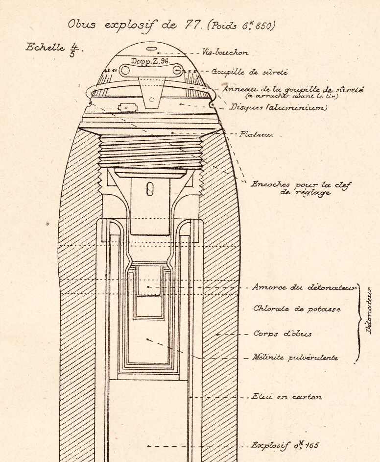
|
This much important mission gave to this often small part of the ammunition one of the most important roles for the correct operation of all the giants, guns and projectiles, that are spoken about in the other pages of this website.
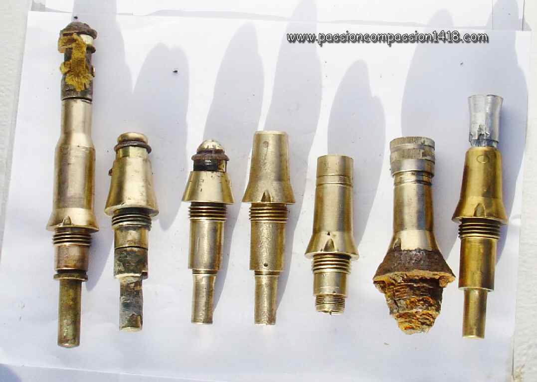
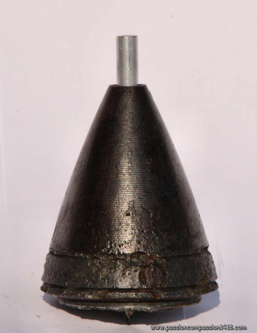
The fuzes that can still be found nowadays in the ploughings, embedded in earth or chalk and half destroyed, are remnants of precision mechanics and pyrotechnics systems... For a good understanding of the explanations and diagrams of the section 'WW1 fuzes', one might want to take some time to familiarize himself with some technical concepts of WW1 fuzes mechanics and pyrotechnics, one of the impressive examples of the human creativity at the service of crime and horror...
Several types of fuzes were in use in 1914-1918. They can be roughly categorized on the basis of the timing needed for triggering the shell explosive charge :
These parts of the artillery ammunitions, designed to trigger the burst at a defined part of the shell trajectory or at impact despite severe conditions before the shell was fired (humidity, shocks, corrosion, ...) and during its shooting (huge accelerations and decelerations, high heat, rapid spin, violent shocks) were remarkable high precision mechanisms. A fuze was also supposed to present all the safety guarantees for the gun crews : it had to be designed in order to sustain uncareful handling during transportation, uncontrolled storage conditions, and the violent acceleration of the shooting start in the tube without causing premature explosions, likely to destroy guns and servants... This additionnal specification added to the fuzes design complexity. It is interesting to note that the trend of the pre-war was to develop more and more sophisticated fuzes, while the war experience, new types of shells and artillery techniques, and war economics induced at the contrary the use or more and more simple fuzes. |
 |
|
The embarked explosive charge of the fuze could be strong enough to trigger the explosion of the main charge of the projectile when filled with gun powder, but with the very powerful modern and more stable chemicals for high explosive shells (for example molten TNT or mélinite main charges), the fuze charge was only igniting a 'detonator' (also called 'intermediate charge' or 'primer') that had sufficient explosive energy to cause the shell detonation. |
 |
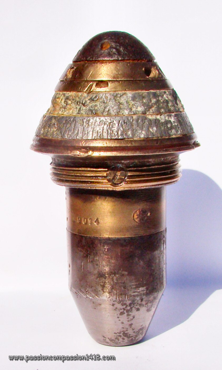
| French detonator | German Dopp Z 96 fuze assembled on a HE shell, showing the primer attached to the tail before mounting on the shell top gaine | |
 |
||
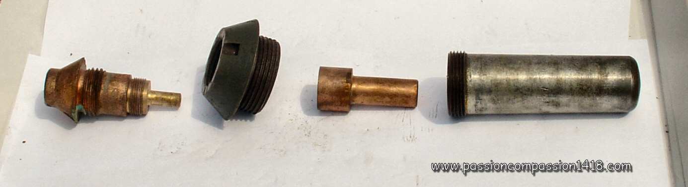
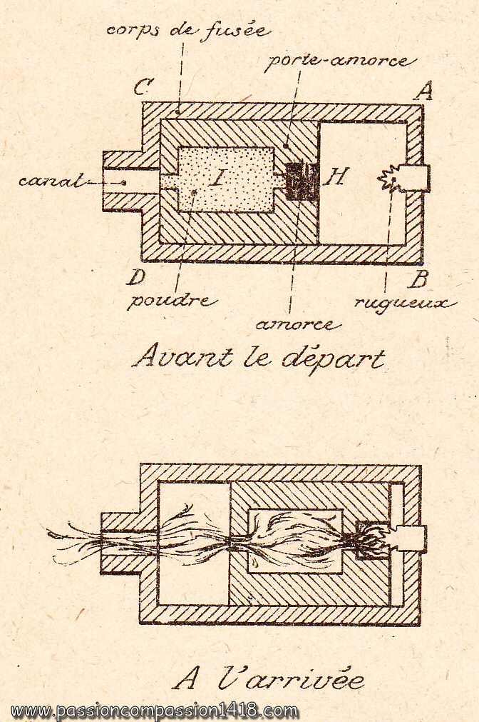
| French 24/31 Typical french high explosive shell pyrotechnic line : from the left to the right, the fuze itself, the adaptator screw ring, the small primer usually screwed on the fuze tail, and the bigger intermediate detonator often mounted into the shell body |
|
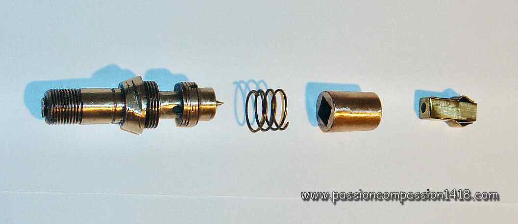
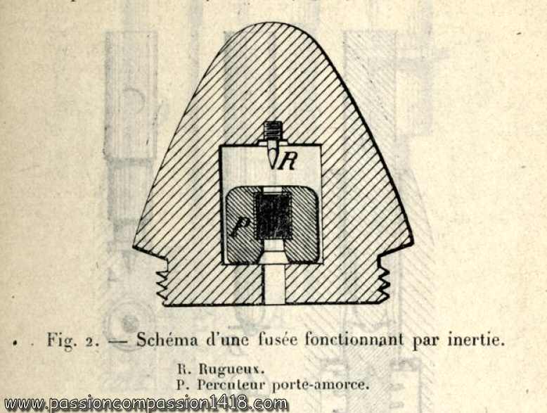
The mechanics inertia principle was widely used in the WW1 fuzes design. Associated with a pyrotechnic igniter that needed the penetration of a hard pin (named 'percussion pin', see an example at left) into a cap filled with a flammable solid (most of the time mercury fulminate, named 'percussion cap'), it triggered a pyrotechnic activation under the effect of an acceleration or a shock. |
|
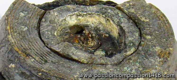
German destroyed discs time fuze, the percussion pin is easily seen in the center of the piece |
||
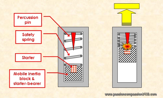
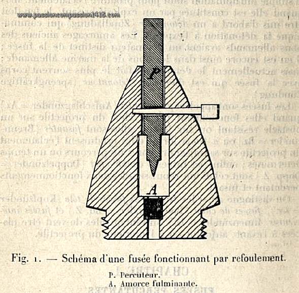
The way the fuzes inertia mecanisms worked was most often comparable to the one exposed in the scheme at right :
|
 |
|
| Simplified classical inertia mechanism of the artillery fuzes | ||
 |
This same principle was applied both for :
|
|
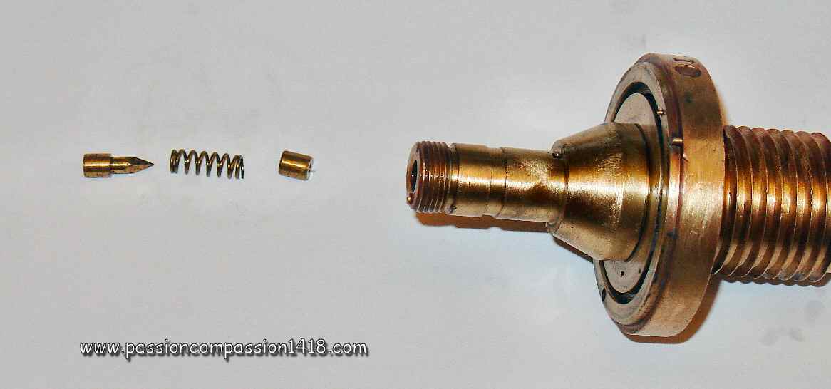
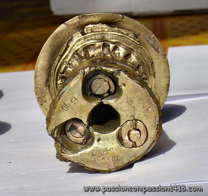
| Time pellet system of a French 30/55 time and percussion fuze. On the picture, from the left to the right : the percussion pin, the safety spring, and the detonator cap. |
||
| In this last case, the apparatus was turned upside down so that the mobile graze pellet was moving backwards. | ||
Fuzes were (and still are...) dangerous pieces of equipment, designed to create a flame, an explosion or even a detonation on a shock or when ignited. Safety devices were necessary to ensure they would not act this way elsewhere than in enemy territory, just when they were wanted to do so. Springs and pins : the basic arming devices Stirrups and ramps : inertia arming systems : At impact on the target, the newly composed graze pellet, fastened together by the staple mechanism, was projected forwards against the safety spring with enough energy to compress it entirely. The detonator cap hitted the percussion pin, and the resulting flame was propagated by a channel machined in the base of the fuze to the main charge. Pyrotechnic arming system At impact on the target, the inertia energy was be sufficient to project the graze pellet against the percussion pin while compressing the safety spring, and ignite the main charge through a base communication hole. Centrifugal force arming system The centrifugal force effects were used in numerous fuzes or detonators safety devices, using different principles, as seen in the following examples :
Uncareful handling during transportation, accidental falls during manipulation, surrounding enemy shelling shockwaves were only examples of so many things that could frequently happen to the fuzes in an usual war environment before their use. Military engineers had to invent safety devices that would inert the fuzes before they were assembled to the shell and shot by the gun.
But another danger existed within the gun itself at the very first instants of the fuze active life : the brutal acceleration of the departure could also cause premature triggering of the fuze and shell explosions still in the barrel, often destroying both the material and its servants... This was another reason for designing safety and arming techniques that would avoid such catastrophies.
Removing the safeties of a fuze is called 'arming'. This could be done manually while the fuze was still attainable, but had to be done automatically from the time it disappeared into the gun breech hole. The corresponding devices are many, and the following list is just intended to give an idea of their varieties, using pins, springs, centrifugal force or pyrotechnics.
Return at the top of page
The basic safety device of a percussion system was the 'safety spring', or 'creep spring', that was inserted between the percussion pin and the detonator cap. This spring could be replaced by, or complemented with an deformable cap protecting the pin, but that would be flattened easily by a sufficient pellet pressure.
These deformable items had to be strong enough to resist to accidental falls of the fuze, but weak enough to be completely compressed when needed at departure or on the shock of arrival. Needless to say that the balance between these two diverging goals was difficult and could eitehr lead to friendly losses, or dud shells...
One simple way to secure completely the fuze was to insert a safety pin (or twin safety pins) into a hole transversing it, that would block the mobile items whose movement was necessary for the triggering process, such as the graze pellet.
This was a real secure system that was used in numerous German or British fuzes. The drawback was the fact it had to be removed manually before the shell was inserted into the gun barrel, and therefore providing no safety from premature explosions in the bore.
Some percussion fuzes used that principle with a safety pin that would be sheared by internal moving pieces only by the impact on target energy.
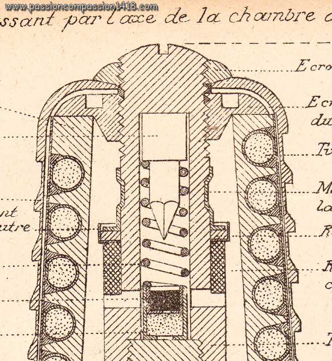
Section of a french time fuze with classical 'percussion pin - safety spring - detonator cap' inertia arming system .
German safety graze pellet secured by a twin safety pin and a deformable cap
Return at the top of page
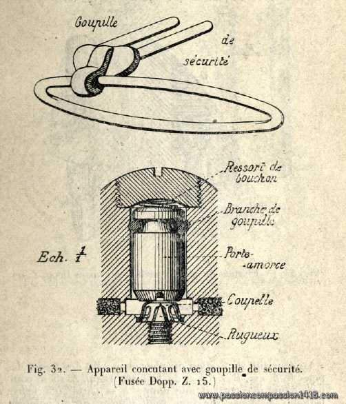
French fuzes often included an auto-arming device, designed to remove a mechanical safety under the action of the shock of departure. This additional safety gave more guarantees than the basic safety spring that was then just kept for providing the in-flight safety, and allowed to avoid safety pins that could be dangerous if accidently removed in the heat of the moment, and were detrimental to the rate of fire since it added an additional operation from the firing crew.
These inertia auto-arming systems all had the same goal of keeping the graze pellet and the percussion pin out of reach of each other before the shot.
French most famous ones were named 'Robin' system and 'Peuch' systems.
Stirrup ('Robin') system
One of these classical French auto-arming systems was the stirrup spring type, appeared in the XIXth century with the 'Budin' (1875) percussion system and widely used during WW1 with the 'Robin' percussion system.
A mobile starter-bearer (or 'detonator cap pellet') was maintained against the back wall of the fuze by an arming spring that was also pressing on an intermediate tubular mobile inertia block, itself kept separated from the front wall and the percussion pin by the classical safety spring.
The inertia block was equipped with a stirrup spring ('staple' being the litteral translation from French). There was no way for the percussion pin to meet the detonator cap in this configuration and the fuze was safe.
Scheme of a Robin type arming system
At the shot departure : under the shock, the intermediate tubular mobile block compressed the arming spring and comes around the mobile starter-bearer. The force was sufficient for the staple mechanism to fasten itself on the notches practised in the starter-bearer : the arming spring was from now on definitely compressed, and a classical graze pellet was reconstituted that way, the safety spring only was now preventing the starter to reach the percussion pin during the flight.
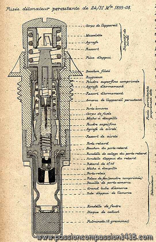
The Robin system has been widely used in French fuzes. One classical example is be the 24/31 Mle 1899/08 fuze
The wartime scheme at far left shows that fuze, using a Robin arming system for the percussion system in the tail and another kind of stirrup system in the top head mechanism ('Lejay' type) for an additional safety. The picture at left shows the remains of such a fuze that can be easily comparred with the scheme.
This mechanism was also used in other fuzes, including the time and percussion fuze 30/38 Mod 1884 and its numerous followers.
Scheme of the fuze in section.
Section of a french percussion fuze with inertia arming system.
A dismantled Budin fuze, ancestor of the Robin system, showing the percussion pin, the safety spring, and the starter-bearer equipped with a staple mechanism that had to be compressed by the departure shock energy in order to enter inside the inertia block.
Helicoïdal ramps ('Peuch') system
Another classical French auto-arming system was the helicoïdal ramps type invented by M. Peuch.
In this system first implemented in 1914 in the fuze 24/31 Mle 1914, and later in the mine-throwers fuze 24/31 Mod 1916, the accidental meeting of the percussion pin and the detonator cap was prevented by an intermediate cylinder that could shorten itself thanks to an ingenieus system of helicoïdal ramps.
Return at the top of page
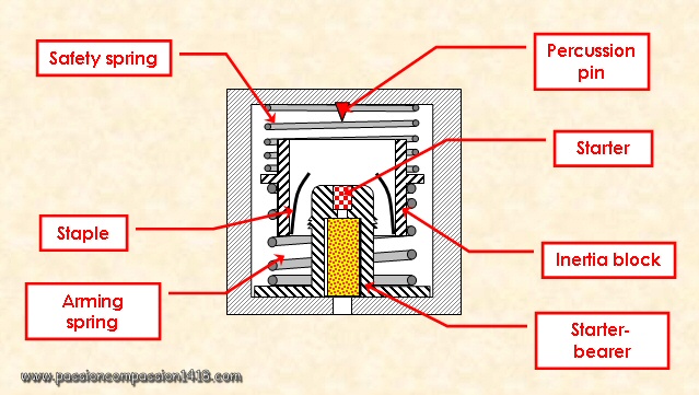
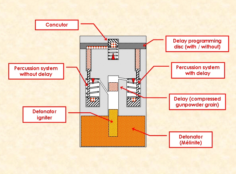
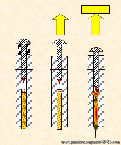
An alternative to the French inertia arming system was introduced by the German military engineers with the pyrotechnic safety. These devices were based on a blocking stem and gunpowder grain system.
This system was widely used in German percussion fuzes as well as in time fuzes. Its advantage was that it allowed to arm the fuze only after the full combustion of the compressed gunpowder grain, that is somewhere on the shell trajectory after leaving the gun barrel. On the other hand, combustion gasses needed some more machining in the fuze for the fumes vents and the necessary igniting system, adding to manufacturing complexity.
In this kind of devices, the classical graze pellet / safety spring / percussion pin system was blocked by a safety stem resting on a compact compressed gunpowder column that prevented any movement.
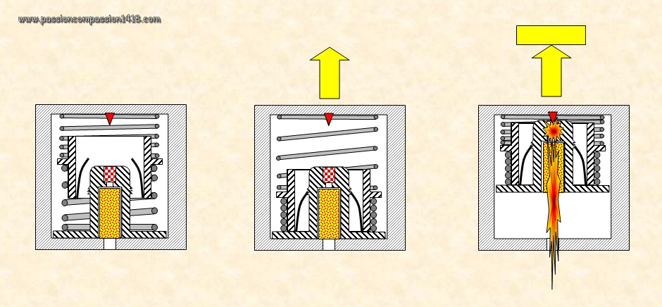
The only way to arm the percussion system was to burn this compressed gunpowder grain. This was initiated at the shell departure either by :
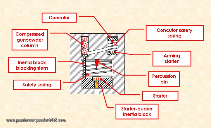
Scheme of a safety stem and gunpowder grain safety system
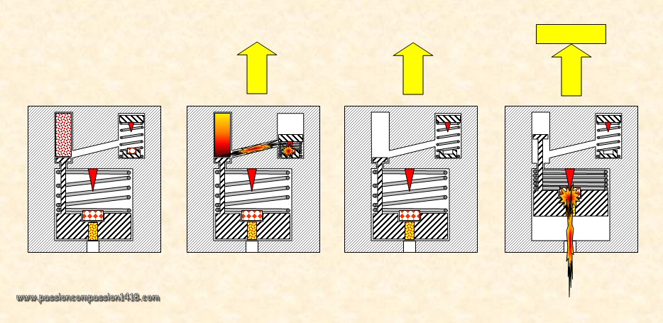
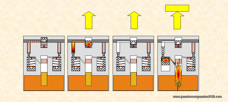
At the shot departure, the shell rude departure acceleration in the gun barrel triggered the concutor mechanism. The resulting flame went through a communication channel to the compacted gunpowder grain that began to burn.
During flight, when the combustion of this powder column was over (this took some time and therefore prevented the presence of an already armed shell in the gun tube, potential source of prematures), the arming device blocking stem was released and the graze pellet was free to move.
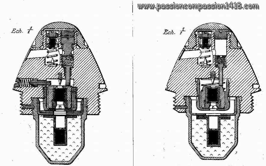
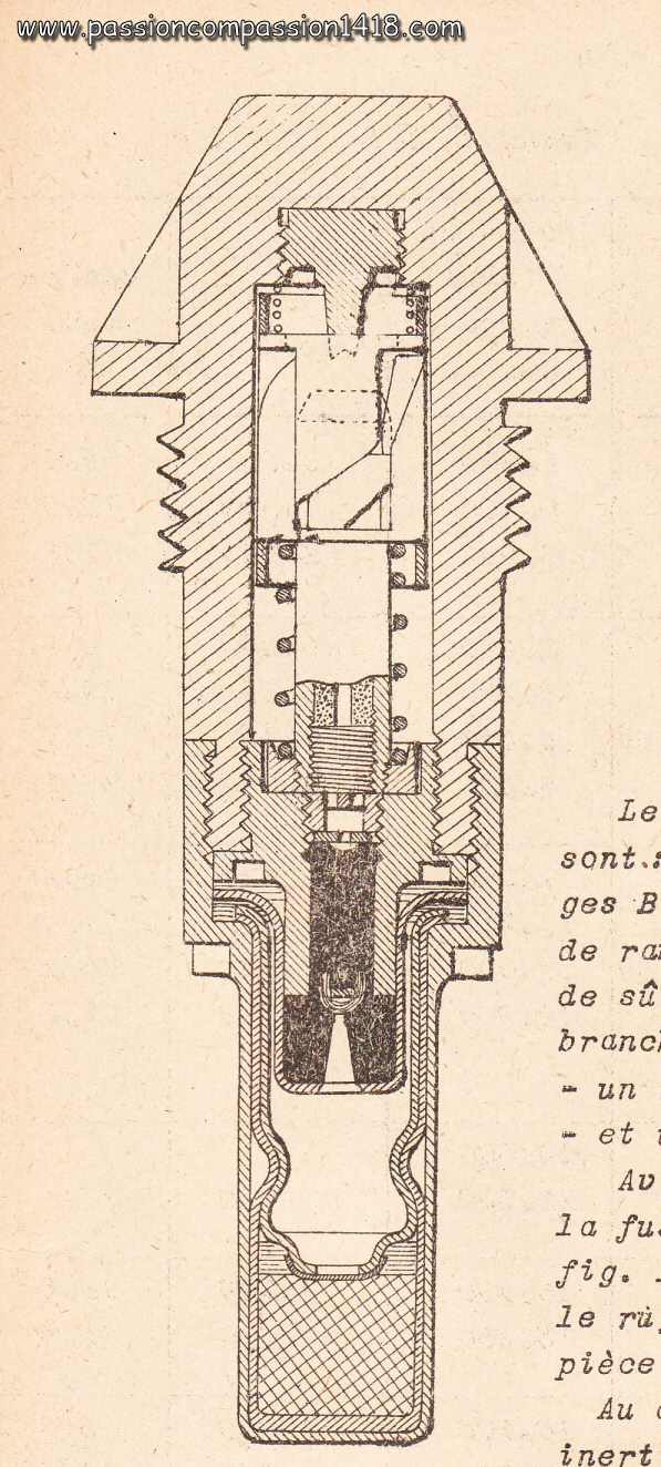
Wartime scheme of the KZ14 German percussion fuze, using the pyrotechnic safety system. One can see the system housed on the top of the fuze in two cylinders, one with the concutor, the other one with the compressed gunpowder grain and the stem, as well as the fume vent.
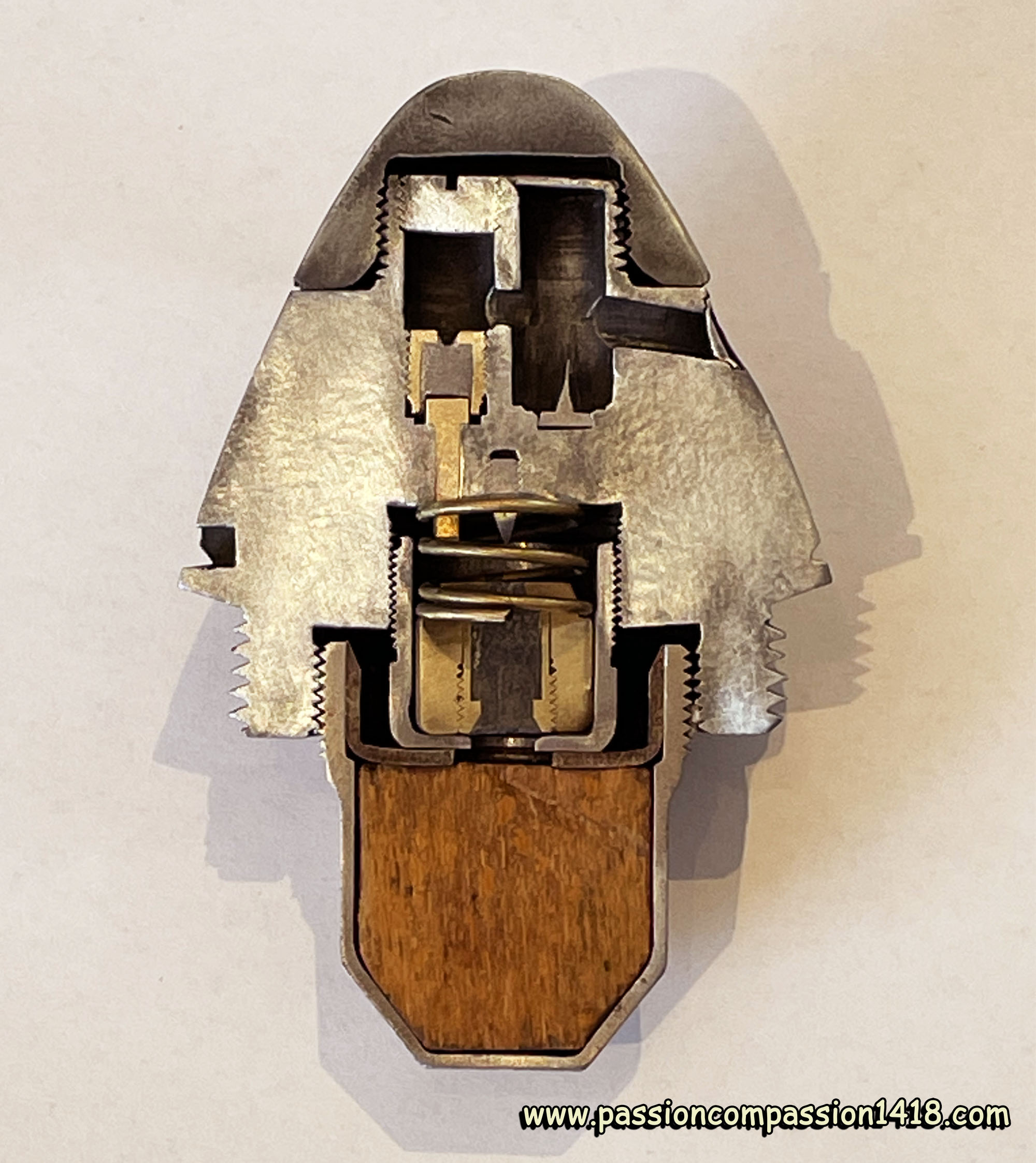
Cut through of a KZ14 fuze. Only the mobile concussion system is missing.
Section of the same fuze, showing the same mechanisms damaged by the explosion.
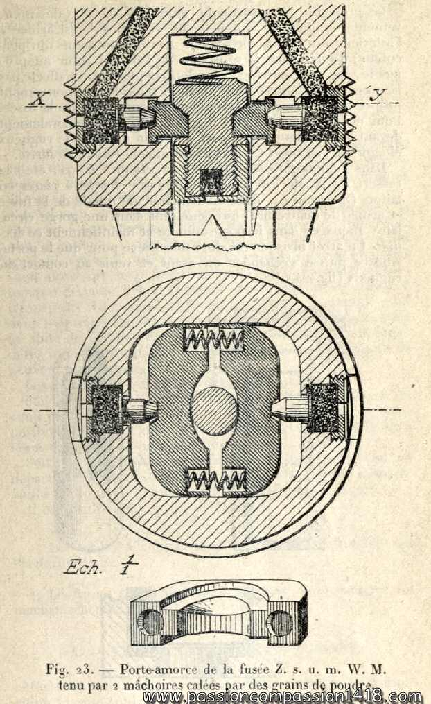
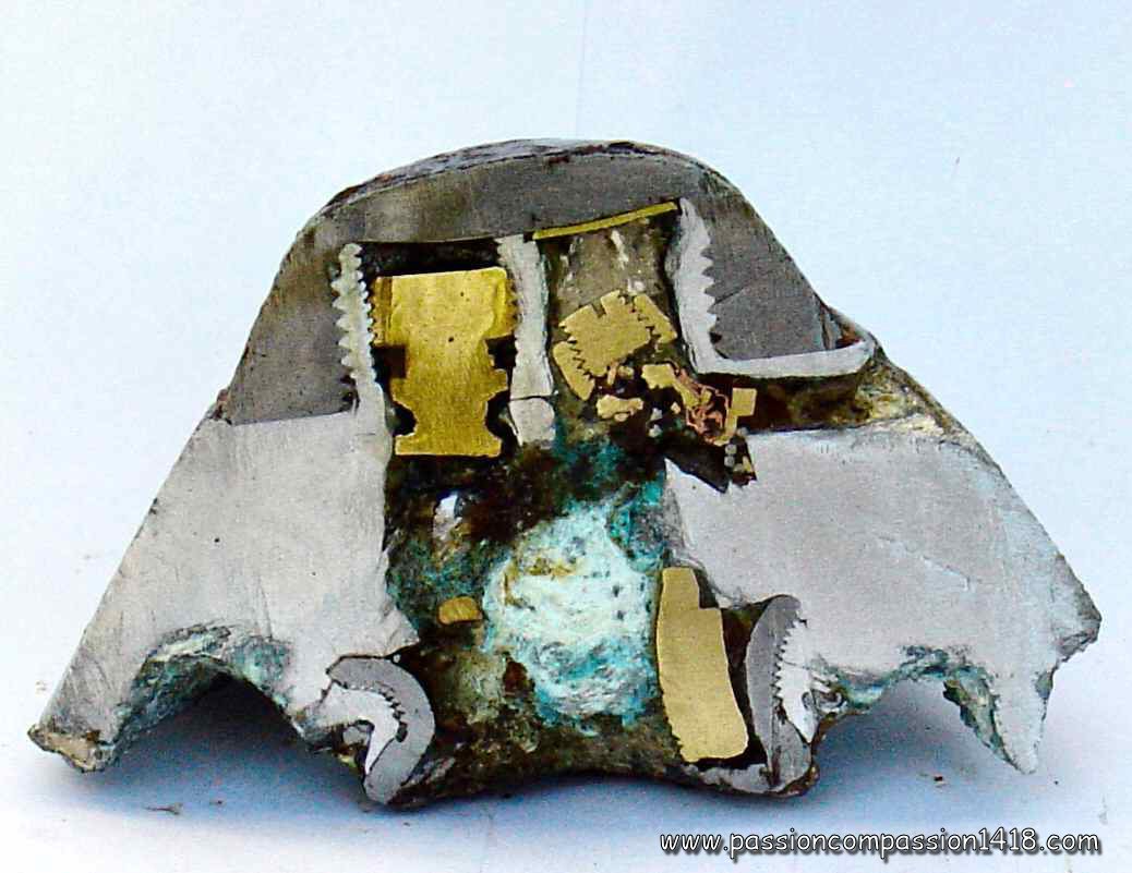
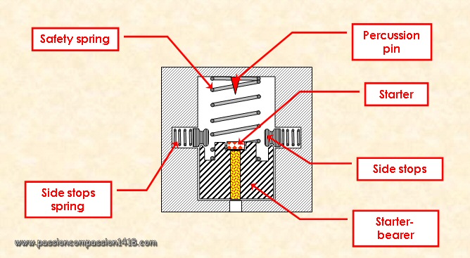
A completely different pyrotechnic safety system was integrated inside the medium and large minenwerfer fuze ZsumMW.
In these devices, the combustion of compressed gunpowder grains ignited at shot departure was needed to allow the action of springs opening metallic jaws that were blocking the movements of the main percussion system at rest.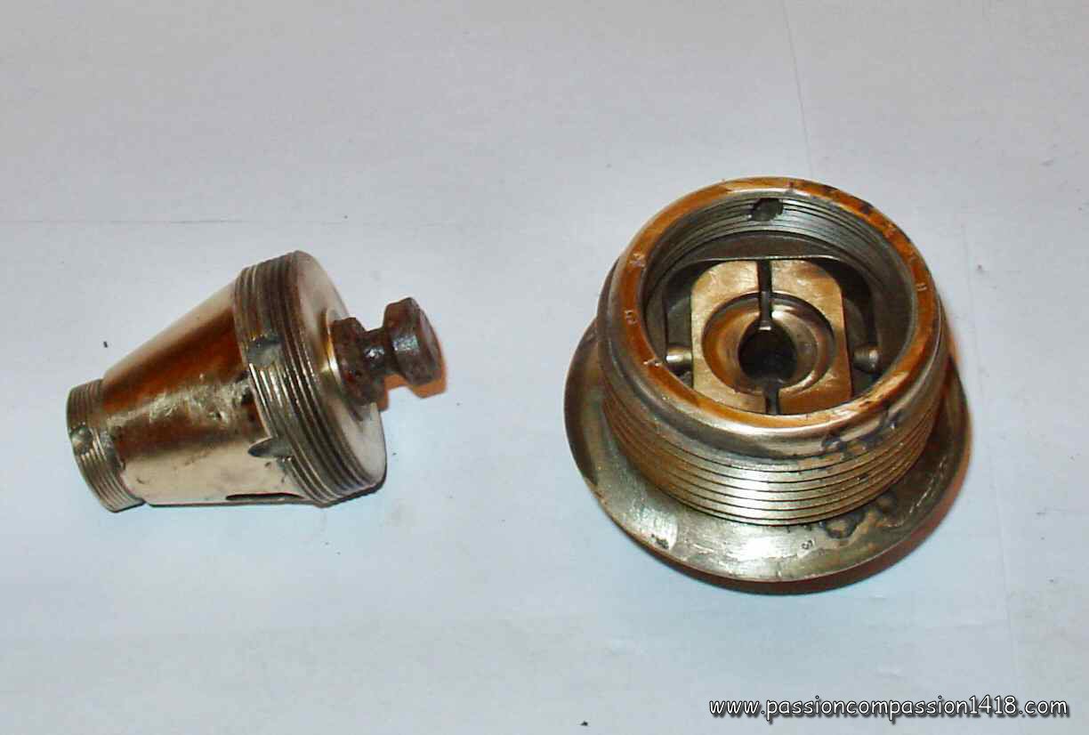
Return at the top of page
Another classical way of arming fuzes after the departure of the gun was to take the opportunity of the spin movement of the shell when fired with a rifle bore tube. This rapid movement gave way to very high centrifugal forces in the shell and fuze.
That effect was mainly used by German fuzes and some British or French ones. One of the specificities of such a phenomenon was that the centrifugal force remains applied to the shell during the whole trajectory, while the inertia needed for stirrup mechanisms was only available during the acceleration par of the trajectory, that is inside the gun barrel.
The centrifugal effect gave way to various systems, and was also used for detonator safety systems.
In the centrifugal force based safety systems, the moving pieces were blocked at rest by side stops resting on springs.
The force needed to arm the system was the one created by the side stops under the action of the centrifugal force to compress the springs.
The pehnomenon coul be computed easily on the basis of the side stops mass, the spring resistance, the shell spin and the fuze geometry.
At the shot departure, the shock had no influence on these systems, but the rotation movement (spin) of the shell given by the gun inner grooves applied quickly a strong centrifugal force (the shell spins at to several thousands of rotations per minute around its axis) to all the elements of the projectile.
Under the effect of this force, the side stops were pushed back towards the walls, compressing their springs, and released the movements of the graze pellet.
From this moment and during the flight, the fuze was armed and only the safety spring of the main percussion system prevented the graze pellet to enter in contact with the percussion pin.
When hitting a target, nothing prevented the impact energy to project the graze pellet against the percussion pin while compressing the safety spring, triggering the shell explosion.
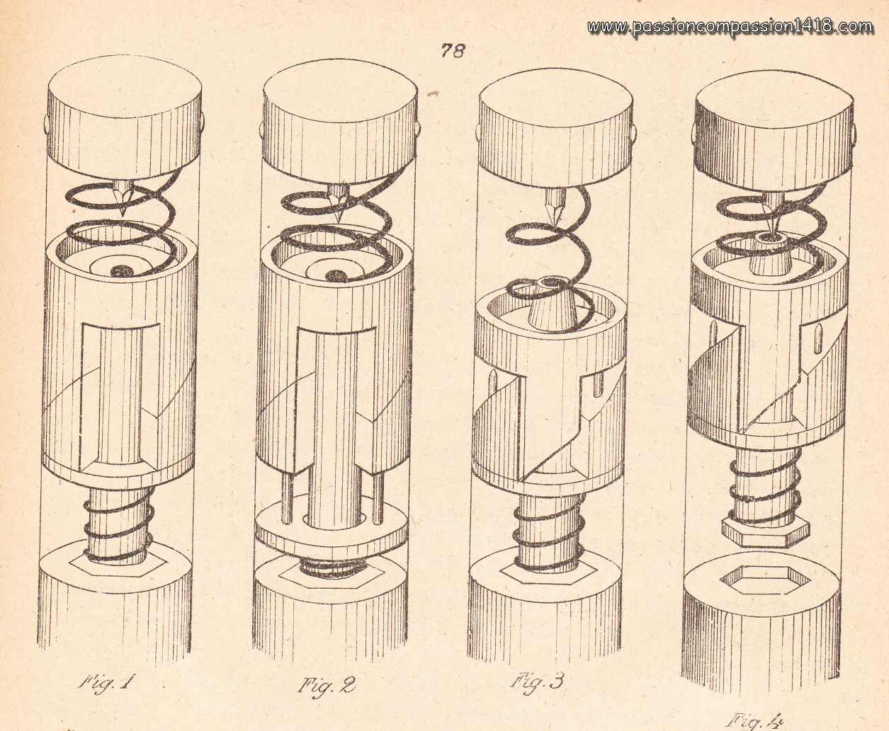
Centrifugal safety locks
were the first and simpler devices using the centrifugal force created by the shelle spin. They consisted basically in a radial rod locking the movements of the percussion graze pellet and maintained at locked position at rest by a small spring.
These devices could exist in a single or twin lock solution, for instance to block the graze pellet of the HZ14 Fliehb. percussion fuze , or the percussion rod of the EHZ17 super-quick fuze 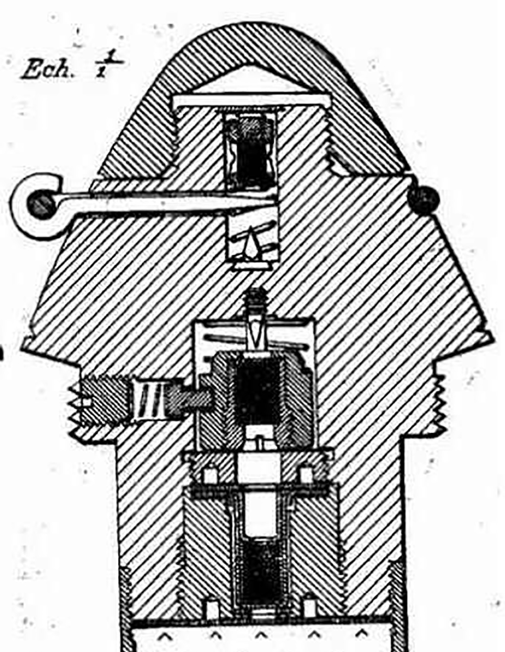
Unwinding centrifugal safety
This simple but ingenious system was used almost exclusively in the French fuzes I.A. model 1915 and I.A.L. model 1916 and is known as the ‘Lefèvre system’. It consisted of two safety half-rings preventing the recoil of a percussion pin, connected to a fabric and brass spiral wound around the half-rings and ending in a steel weight.
During its journey through the tube, acceleration would tighten the coil to prevent premature bursting, but upon exiting the tube, this would cease and the centrifugal force created by the rotation of the shell would unwind the coil and eject the half-rings. 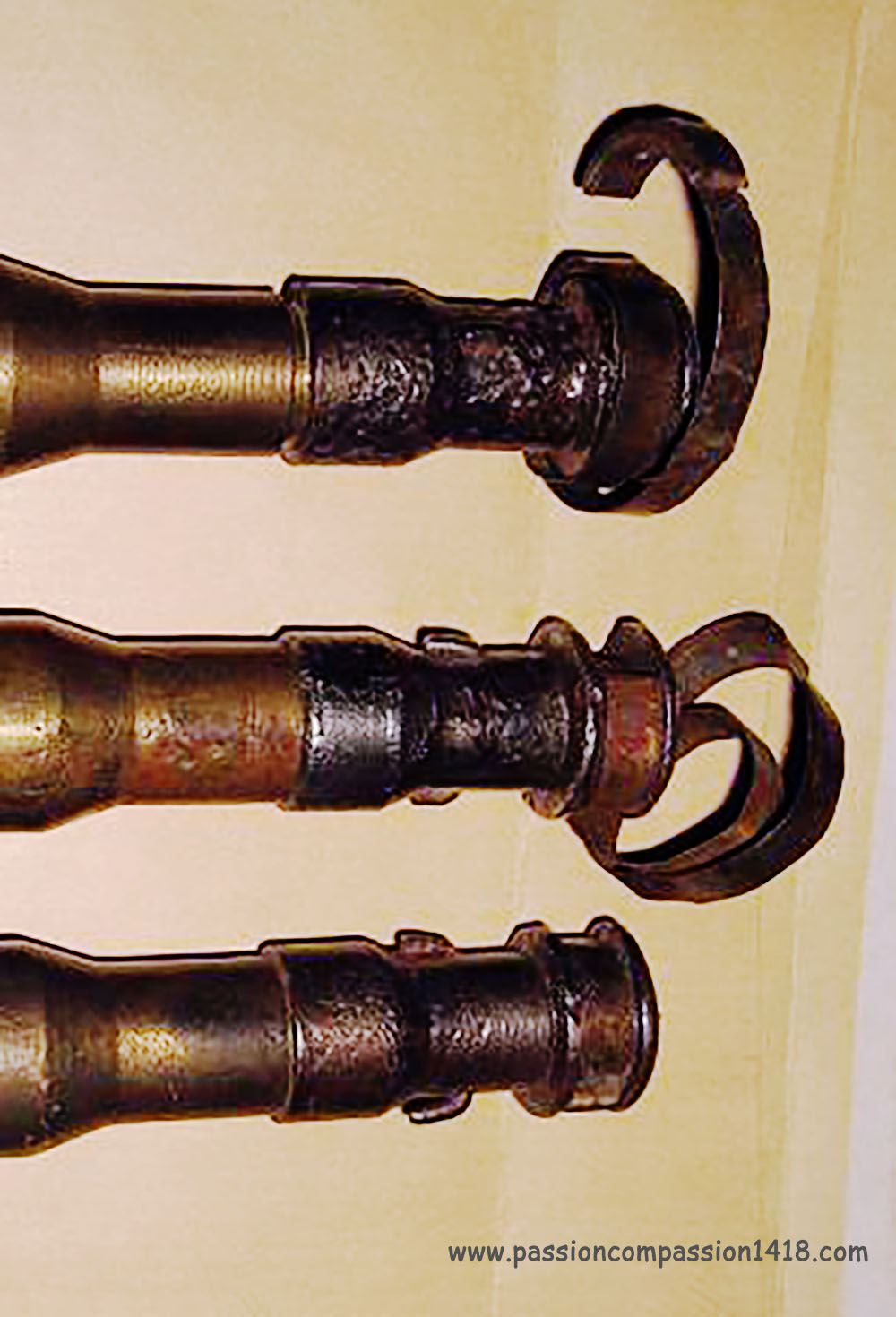
Rotating bolts safety locks
seems to have been introduced first in the German navy fuzes, then used in many army ammunitions.
The device was made of a number of rotating bolts on eccentric pivot aligned in circle, as a photographic diaphragm. In closed position at rest, the bolts would rotate under the effect of the centrifugal force, opening a way in the middle. This was often cleverly designed so that the 'petals' rotation was not allowed while the projectile was accelerating in the barrel.
This system was able to block either a percussion system graze pellet movements, or the percussion rod of super-quick percussion fuzes, such as this GRZ16 and this GRZ17 fuzes
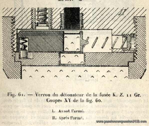
Sliding drawer safety locks
was uniquely dedicated to prevent the flame from the fuze to reach the tail detonator.
This was therefore an additional safety device, often adding to one of these described above, should they fail in their mission. The design was based on a sliding polygon drilled with a hole, that could move transversally in the fuze base. It was maintained at rest in a central position obturating the pyrotechnic line. Under the effect of the centrifugal force during the flight, the lock moved laterally until its central hole was opening the flame communication channel to the detonator.
This sequence is illustrated in the KZ11 Gr fuze scheme aside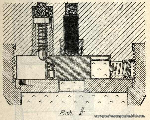
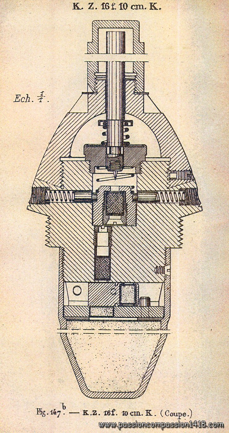
Some or all of these safety devices could be combined together, like in the left-hand KZ16.f.10cm.K fuze including, from the top to the bottom :
This created increasingly complex percussion fuzes, hiding a surprising number of components under seemingly simple and rough envelopes, like the EKZ16c fuze below

Percussion fuzes were designed to trigger the burst of the shell when hitting the ground, an obstacle or the aimed target. Originally dedicated to siege guns and projectiles, they became more and more used during the war with all guns including the fieldguns, with the progressive replacement of the classical shrapnell shell for anti-personnal missions by HE shells, inspired by the trench war experience.
Depending on the type of target to be destroyed, it could be necessary to fine tune the precise moment of the explosion in relation with the moment the shell body itself would impact the target.
Yet at the beginning of the war, HE shells fuzes could be equipped with delay systems that would trigger the shell burst some hundredth or tenths of a second after the impact, allowing the shell to perforate a protective coating of concrete, wood or shielding before exploding. During the war, this kind of behavior proved very useful against trenches, deep dug-outs, tanks, or even to create large craters, or to let gaz shells liberate their poison slowly from the ground.
The war experience also induced the fighting armies from each side to feel the need for a percussion fuze that would act so quickly that it would trigger the explosion of the shell before the warhead really entered into the ground or the target. This is how superquick fuzes were invented and mounted on HE shells for anti-personnal, barbed wires destruction or gaz spreading missions.
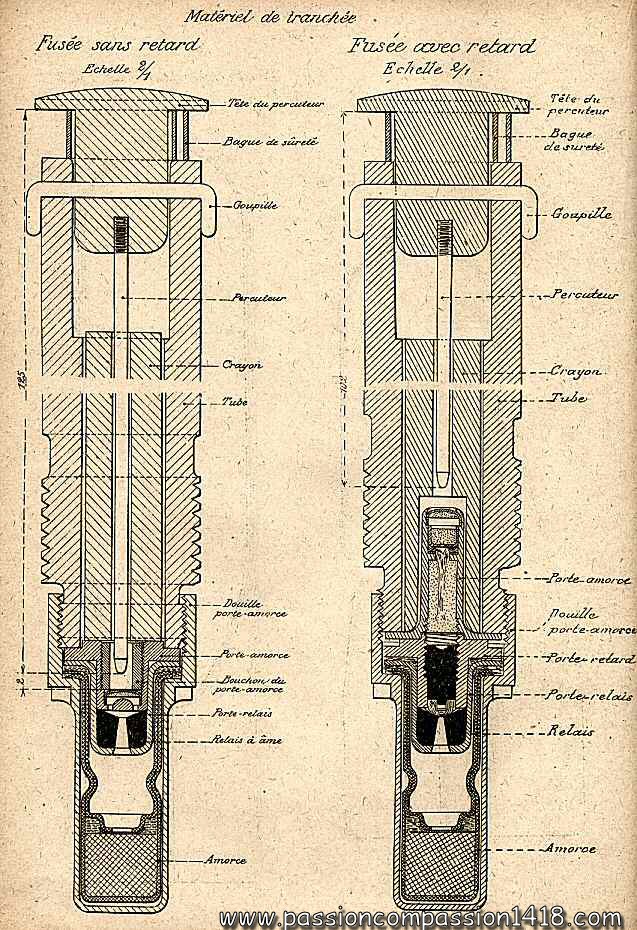
Non delayed percussion fuzes
 |
At the beginning of the war, 'percussion fuzes' (also named 'direct action fuzes') mainly equipped the siege and naval guns. They were based on the percussion system described above, with a mobile graze pellet and a percussion pin (and hence sometimes named 'graze-action fuzes'). One of the classical concerns of such fuzes was their safety, since their users wanted them to burst the shell when hitting the target, but not when accidently hitting the ground due to a mishandling. Different arming systems were found and used (see above). Such basic fuzes could malfunction (not exploding) when hitting a ground too soft, or slowed down in water. |
 |
| Theoretical scheme of a German pure direct action fuze based on inertia system. |
Delayed percussion fuzes
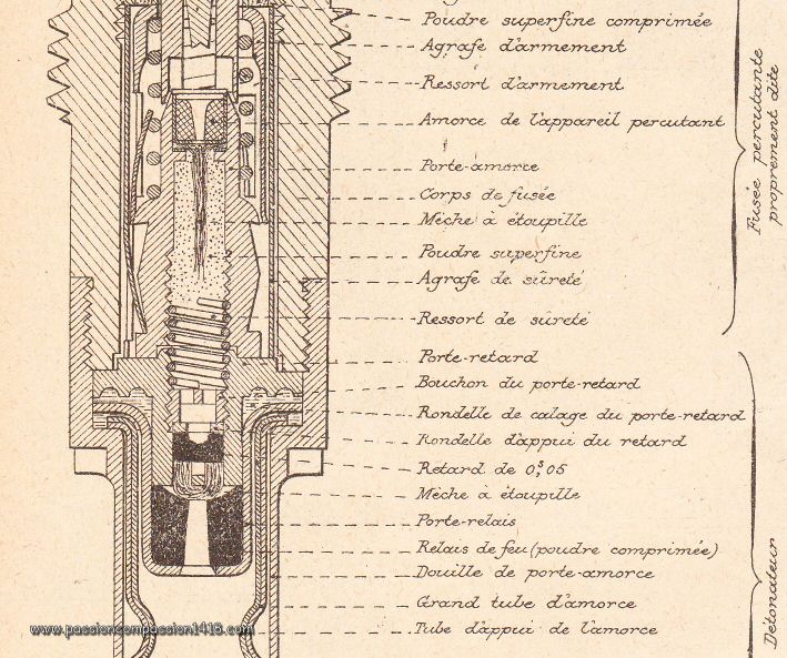 |
Classical direct action fuzes could prove inefficient when hitting a steel shield or a reinforced concrete surface. In both cases, the shell would burst before it could penetrate into the hard surface, and the shield would be left almost intact. Delaying the fuze action for less then a tenth of a second would let the shell enough time to pierce the shielding and explode behind it or into it, with much more damages. This result could be obtained by inserting a delay (a tiny compressed gunpowder grain) in the classical pyrotechnic line of a percussion fuze, between the graze pellet inertia system and the detonator. This kind of fuze was also found pretty useful with some kinds of gaz shells when the desired effect was that the projectiles digs himself into the ground and slowly liberates its poison for a zone interdiction, against fortresses with perforation shells (with specific fuzes inserted into the shell base to avoid their premature destruction on the concrete), or against tanks. |
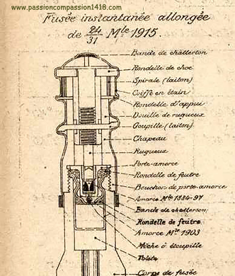
| Zoom on the pyrotechnic line of a French 24/31 Mle 94/08 percussion fuze including a small 0.05 sec delay just before the detonator. |
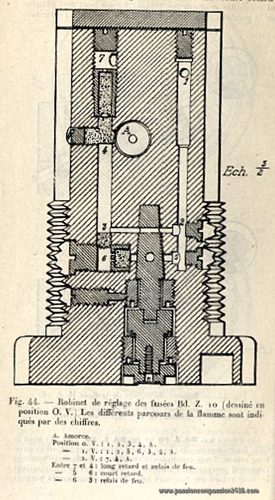
| Whereas French and British fuzes were most of the time originally built with or withour delay, or could be quickly adapted by inserting a delay into the tail, the German engineers wanted to create polyvalent fuzes with selectable delays. This behavior was obtained either by the use of :
Later in war, this kind of complex selection mechanism was less and less used and replaced by delayed or non-delayed fuzes easier to manufacture and to use. |
 |
|
 |
 |
|
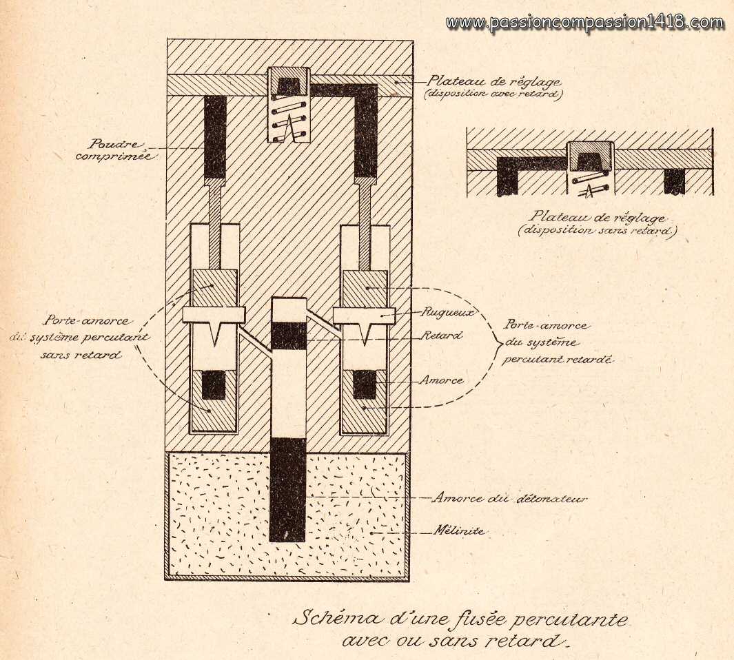
| Wartime scheme of a theoretical selectable separate pecussion systems | Wartime scheme of the BdZ10 base fuze delay selection system, based on a single percussion system whose flame could be directed to different channels delayed or not, by the means of an external selector screw. | |
Operation of the selectable separate percussion systems type :
 |
Position 'No Delay' ('o.V.') : At the shot departure, the arming percussion system flame is directed to the compressed gun powder grain that blocks the movements of the stem maintaining the no delay percussion system and burns it. At the impact, the 'no delay' percussion system works while the delayed one is blocked, and its flame is immediately transferred to the detonator via a communication channel passing under the delay. |
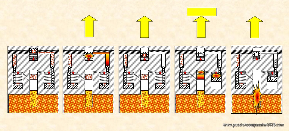 |
Position 'With Delay' ('m.V.') : At the shot departure, the arming percussion system is now directed to the compressed gun powder grain that blocks the movements of the stem maintaining the delayed percussion system and burns it. At the impact, the delayed percussion system works while the non delayed one is blocked, and its flame is transferred to the detonator via a communication channel including a delay. |
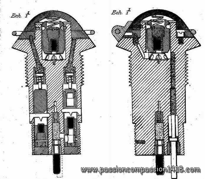 |
This kind of selectable delay systems gave way to very complex material, as it can be seen on this German percussion fuze with optional delay GrZ04. The left picture shows the inner scheme with the two separate percussion systems, while the right one is a tail view of the same fuze showing the complex inner organization with the holes of the two percussion systems and different safety systems. This complexity was a real handicap in wartime economy, and the new fuzes designed during war were much simplified. |
 |
Super-quick percussion fuzes
 |
The need for a new kind of fuze came early during war, for all fighting nations : the applications seemed numerous for a system that would detonate the shell before it penetrates into the ground. This is how the idea came of a very simple system based on a solid rod pointing forward on the top of the fuze and pushed back when hitting a target. This pure rigid mechanical effect proved quicker than the inertia / spring based systems, and the rod top position far ahead from the shell was another factor inducing a burst before the shell enters into the earth. Moreover, these systems could be made much more sensitive that the inertia ones and trigger when hitting 'weak' targets, provided specific safety devices were added... The typical use of these ammunitions were mainly :
At the end of the war, with the massive use of gaz shells or high explosive shells instead of shrapnel by the field artillery, these kind of fuzes became almost predominant, and it is not surprising numerous new designs were made from 1916 to 1918 by all fignting nations. |
 |
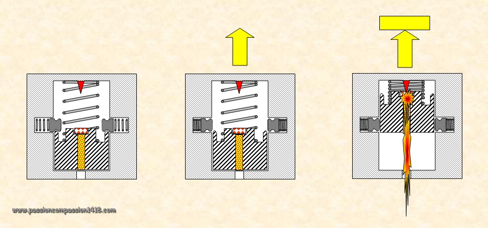
The basics of such a 'push-back fuze' (more often called 'superquick fuze' or 'intantaneous fuze' can be seen on the very simple French mine-thrower fuze on the left, and schematized on the right. In this example, the only safety mechanism is a safety pin that was sheared by the rod when hiiting the target. It is intersting to notice on the left tha a variant existed for this superquick fuze with an additional delay !!! One must remember that in the case of trench artillery the use of sensitive superquick fuzes was dictated by the nature of the grounds and low projectile speeds and not by the need to maximize surface effects. In the other example top left (French I.A. fuze), the long rod has been replaced by a short one, the whole percussion mechanism and pyrotechnics being located on the top of the long fuze, and linked to the shell body via an explosive wire. |
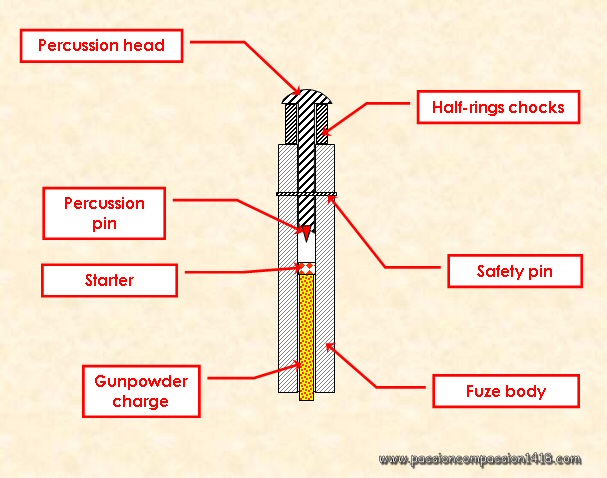 |
| At the shot departure, the half-ring chocks were ejected by the centrifugal force of the spinning shell, or were removed manually in the case of the trench mortars. During flight, the percussion rod was prevented to slide in the cylinder despite the wind pressure, thanks to the mild steel safety pin. When hitting the target, the head of the striker hitted the target at full speed, the rod was drove back in the tube and the mild steel pin was sheared by the shock, letting the percussion pin encounter the starter, triggering the detonation. Obviously, this operation needed that the shell attaining the obstacle with a good perpendicularly compared to the axis of the stem. This was generally the case for the indirect curved shots of the trench artillery with fin tailed projectiles, for howitzers projectiles shot at high angles, or for the field guns direct flat shots against standing obstacles. |
 |
 |
 |
 |
| Varitaions of the French superquick fuzes | Theoretical scheme of a typical German superquick fuze, that usually kept an ogival shape, sometimes elongated. | 1917 version of the German Fieldgun superquick fuze 'EKZ17' |
Shrapnel shells were in 1914 the main ammunition in use by the fieldguns of all the fighting nations. Just as with the older fragmentation shells, the efficacity of their anti-personnal effects was dependant of the position they bursted just in front of their target, in order to sprinkle steel fragments and lead balls on it. Since there is no impact of the shell with the target to give the signal for the burst, the fuze had to be a precise mechanism integrating a count down.
The role of the 'time fuzes' devices was to trigger the explosion at the end of a given lapse of projectile flight time (generally from some seconds to almost a minute), corresponding to the distance needed, given the knowledge of the projectile speed.
Pure time fuzes were generally limited to the use of Anti-Aircraft artillery, where one wants the shell to burst around the flying target but where it is important that an unexploded shell does not explode when landing back on friendly land. Most of the time, these systems were associated with a percussion mechanism, making these fuzes 'Time an Percussion' fuzes.
Three main types of time fuzes, were in use during WW1. Two of them were based on the slow and regular combustion of 'pulverine' (compressed gunpowder) track with an approximate speed of 1 cm a second, and the third one appeare lately and was based on clockwork mechanics :
Tubular time fuzes
 |
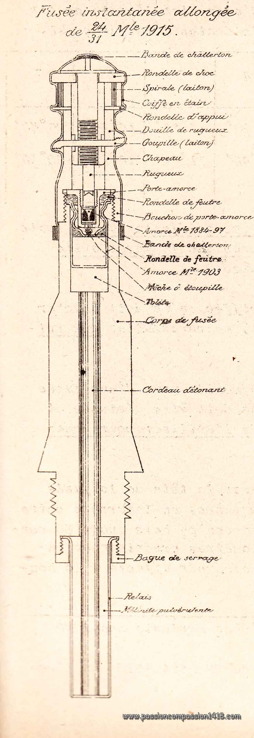
This kind of time fuze was exclusively used by the French artillery, for instance with their famous fuzes '22/31 mod. 1897' (whose wartime scheme is shown at left, and a surviving example at right), or the '30/55 mod.1889'. The following explanation is made for the first model, that was equiped of an additional classic percussion fuze device in its tail. This particular fuze thus was a 'double-effect' (or 'time and percussion') one. |
 |
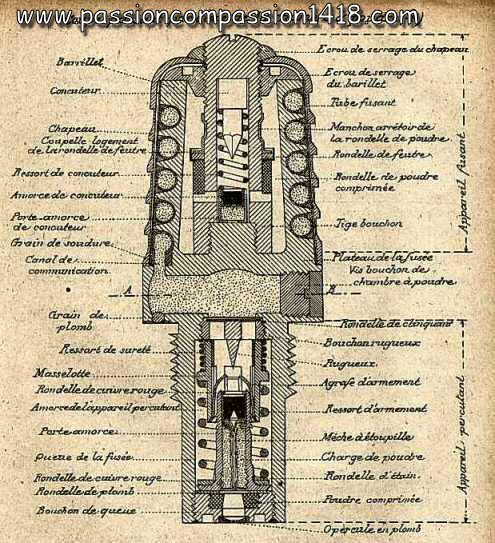
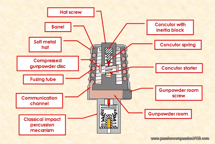
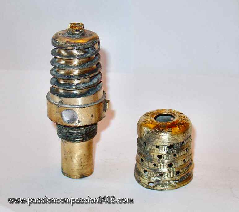
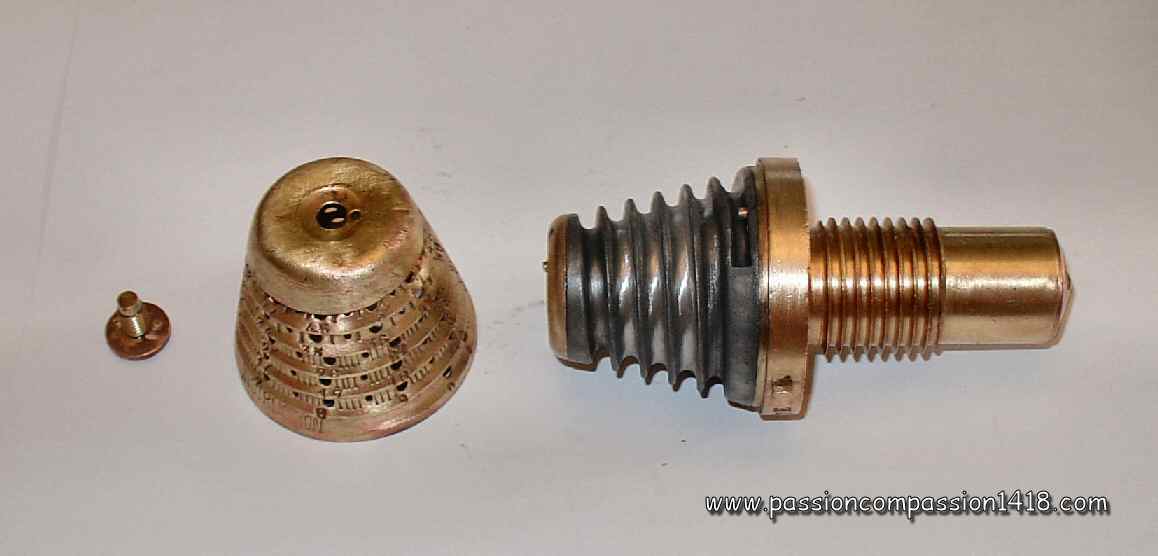
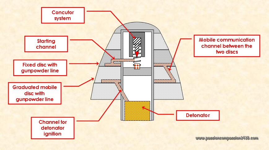
| In this fuze, a stretched lead tube containing the compressed gunpowder is rolled up in a spiral shape along a hollow conical barrel. In the inner housing of this barrel is lodged an time pellet (also called 'concutor') inertia system designed to ignite the time system track at the shot departure, as well as a compressed gun powder disc. The lower part of the spiral tube was connected to a gunpowder room, placed under the barrel, just above a traditional percussion fuze device. The barrel and the fuzing tube were covered with a 'soft metal hat', engraved with a spiral groove just over the path of the fuzing tube, in which seconds graduated marks were stamped. |
 |
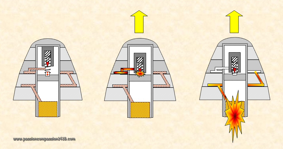
Operation of the tubular time fuzes :
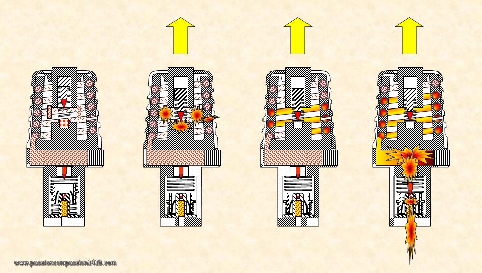 |
For a time-triggered behavior, before the shot the artillery man punched the hat groove graduation at a precise place using a specific equipment called 'fuse-borer' (in French 'débouchoir'), according to the aimed time of flight before explosion, given by the battery officer. This operation made a communication between the compressed gunpowder of the fuzing tube and the inner room of the barrel. The shell shock of departure in the gun activated the concutor (or time pellet), that started the combustion of the compressed powder disc. The flame of this disc was communicated to the compressed gunpowder of the fuzing tube just at the punched place, and the two tube sections began to burn in two opposed directions, at the speed of 1 cm a second. When the combustion of the lower section reached the lower gunpowder room, the explosion of this latter passed through the percussion apparatus to ignite the burst charge. |
 |
For an impact-triggered behavior, in the case of the double effects fuzes only, the explosion could also be caused at the impact time if that one occured before the end of the flight time selected by the punching of the time groove, or if the fuze cap had not been punched and therefore a pure percussion behavior selected. In this case, the explosion was commanded by the lower traditional percussion fuze system. It is worth noting some fuzes were not equipped with a percussion mechanism. In that cas they were called 'simple effect time fuzes' or 'time only fuzes'and were dedicated mainty to the Anti-Aircraft shells that no-one wanted to burst when coming down to the friendly ground in the case of a failure of the time system . |
This system, called 'French Time System', was derivated into several fuses models until WW2.
 |
 |
 |
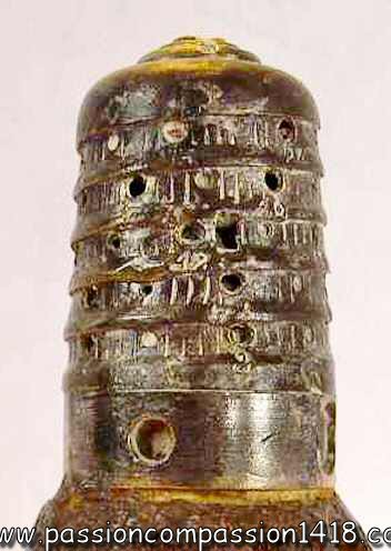
| Fusing spiral groove of a French 25/38 Mle 1880. The lead inner barrel has been pierced at the place of a graduated cap hole | Family picture of several French fuzes derivated from the French Time System, including some pre-WW2 fuzes. | Fusing spiral groove of a 30/55 Mle 1884 French fuze |
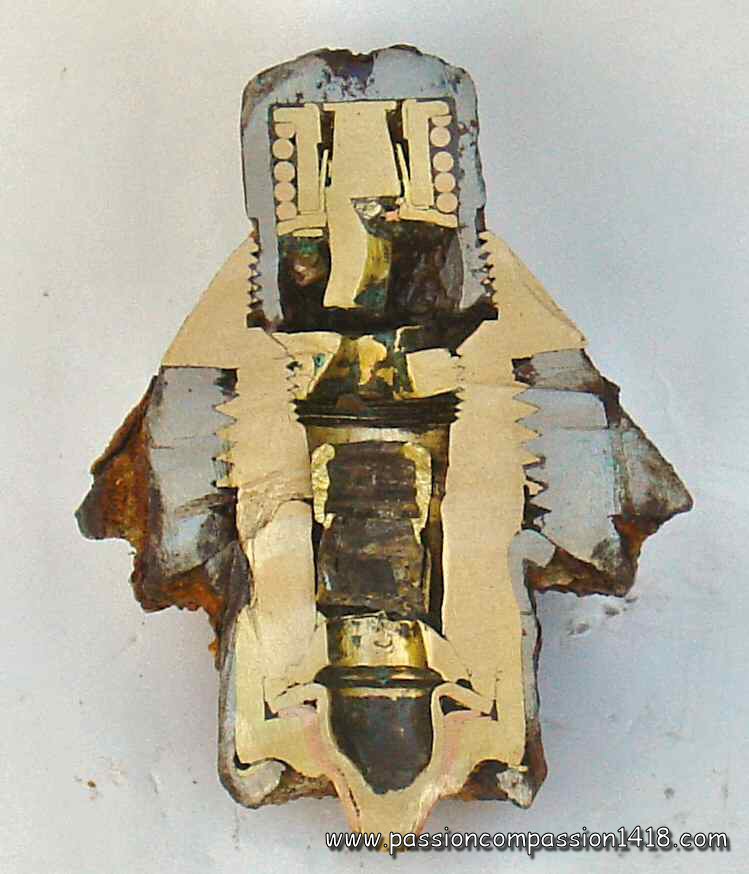
Revolving discs time fuzes
 |
Apart from the French Army, all of the other nations used the revolving discs time fuze systems rather than the tubular time systems. Almost as quick to set up than the tubular time fuses (whose sometimes fragile mechanism was one of the contributing conditions to the impressive shooting rate of the 75 mm gun), they were however somehow easier to manufacture but on the other hand required more metal. Again, most such fuzes were equipped with an additional percussion system that gave them a selectable percussion fuze behavior that could be selected intentionally, or would act if the time system failed or did not finish its countdown before hitting the ground. In this case, these kind of fuzes were called 'double-effect' or 'time and percussion' fuzes. |
 |
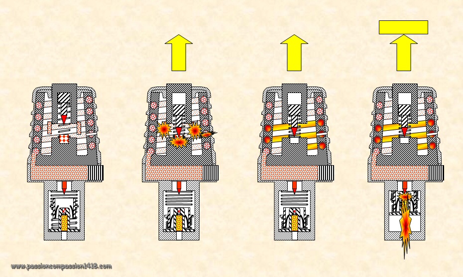
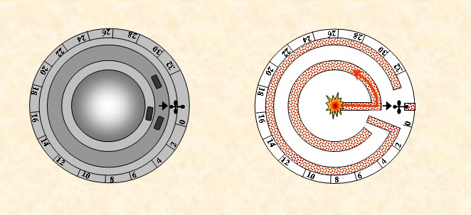
This time, a track of compressed gunpowder powder is located in circular channels dug in the base of two superimposed metallic discs, one being mobile (by rotational movement) and the other fixed. Both these channels are interrupted on a small segment of their circumference. The gunpowder line of the higher disc (fixed) is connected at one end to the concutor placed in the axis of the fuse, via a connection channel.
The gunpowder line of the mobile lower disc is connected at one end the burst charge of the detonator located at the base of the fuse axis. A communication channel, machined in the mobile disc makes it possible to connect the higher and lower gunpowder lines at a selected place, just by rotation of the mobile lower disc |
Operation of the revolving discs time fuzes :
 |
The shock departure of the shell caused the operation of the time pellet ('concutor') system, igniting the gunpowder line in the communication channel. The flame progressed at an approximate speed of 1 cm a second, successively in the upper fixed disc gunpowder channel track until the moment it reached the mobile communication channel whose position was set up by the disc rotation, then the lower disc gunpowder line. The combustion of this one lead the flame to the burst charge whose firing finally commanded the detonator explosion or the one of the shrapnel shell rear charge. |
These fuzes setting was realized prior to the shot by the rotation of a graduated mobile disk, placint the desired flight duration value (in seconds or hectometers) in front of an index engraved in the fix disc or fuze body. Inner parts were designed to immobilize the mobile disc before the shot, in order to prevent it to rotate during the flight under the action of the shell spin forces.
 |
These fuzes generally were 'double effect' type, pure 'percussion behavior' could be selected pointing the index on the (international !) Roman Cross symbol. In this configuration, the gunpowder tracks of the discs did not communicate, and the combustion stopped when the higher track was burned. Only the traditional percussion system integrated in the fuze could then trigger the shell explosion at the impact time. |
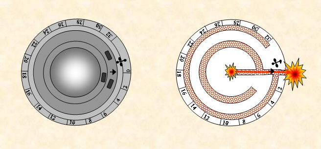 |
When the index was positioned on the '0' mark (sometimes at the place of an evacuation vent for the fumes), the two communication channels were aligned, so that the detonator ignition was quasi instantaneous, corresponding to the needs of a grape-shot firing at point blank. |
 |
All other positioning of the index induced a time counting behavior, whose duration was shown by the engraved figured of the lower disc, pointed by the index, and corresponding to the combustion time of the sum of the gunpowder lines. |
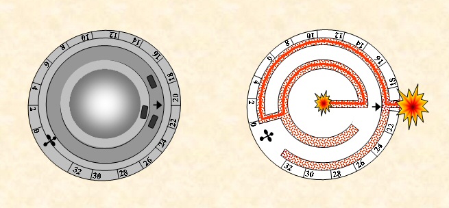 |
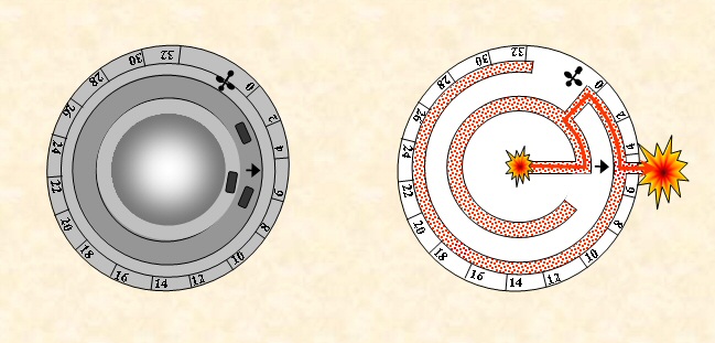
Increasing the angle allowed to increase the flight duration time |
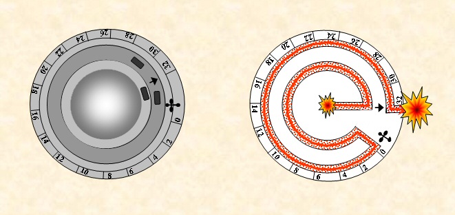 |
The maximum duration was reachable by the time needed to burn the sum of the circumferences of the gunpowder lines of the two discs. |
The maximum set-up time could be increased for long range guns in specific fuzes by using a slower burning composition for the gunpowder track, or by increasing the number of discs.
The combustion of all these gunpowder tracks and elements generated smoke, so that multiple windows were machined in those fuzes in order to let the gasses escape.
 |
 |
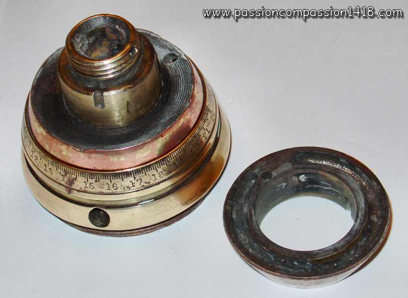 |
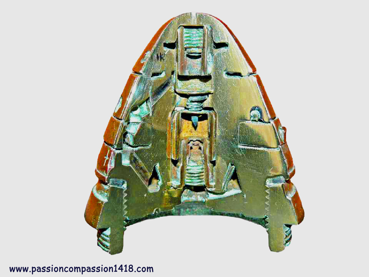
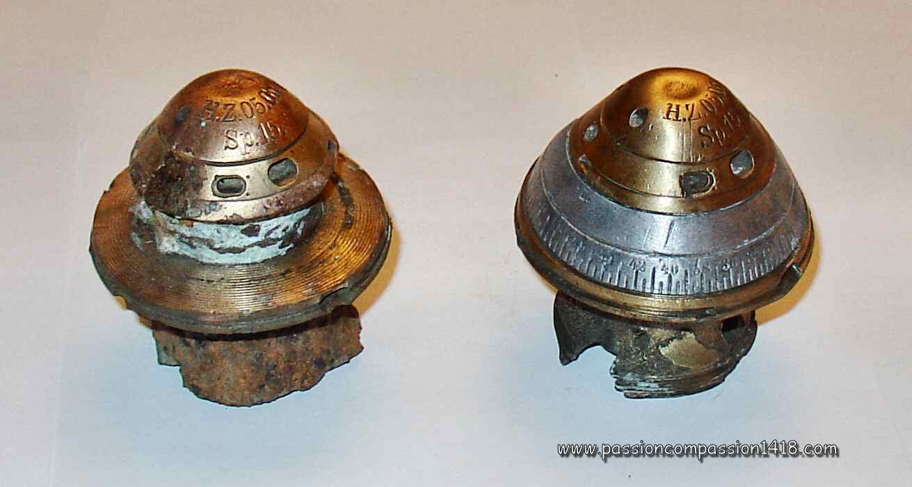
| Superb section made by Alain Dubois of a British n°80 time and percussion fuze. See the communicating channels between the discs | Revolving discs German HZ05 time and percussion fuze : the destroyed model shows the sliding grooves of the disappeared mobile disc | Opened British n°80 time and percussion fuze, nice view on the central housing where the time pellet was located. |
 |
In the few cases where the explosion when hitting back the ground was prohobited, such as in anti-aircraft missoions over friendly territories or with some special ammunitions, simple effect timefuzes were also available. This could be obtained with a dedicated fuze design, but most of time simply not installing the percussion mechanism in a classic double effect time fuze body (in the manufacture) was sufficient. |
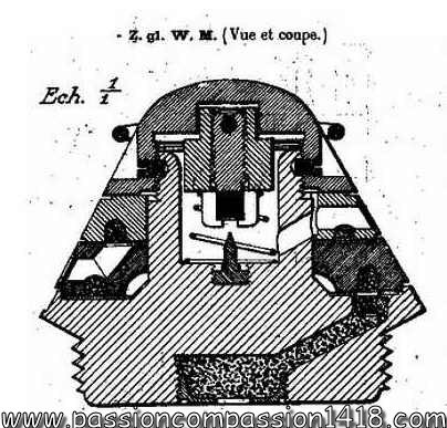
Clockwork time fuses
An alternative to pyrotechnic systems, entirely mechanical, was also adopted by Germany and France with the rare clockwork fuzes. Indeed, systems based on the burning time of a compressed powder trail had a few drawbacks:
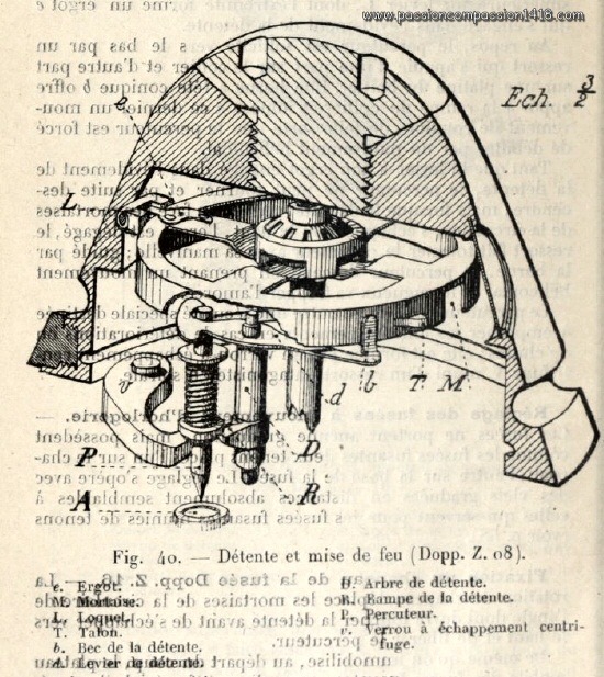 |
In the vast majority of practical use cases, these disadvantages were negligible, but for shrapnel fire at very long distances (e.g., for long-range artillery adjustment fire) or for anti-aircraft fire (where the shell encountered large variations in atmospheric pressure and temperature during its ascent), they caused inaccuracy in the timing of the explosion along the trajectory, which could be unacceptable. The mechanical devices of these alternative fuzes were based on civilian technology that was well mastered at the time (watchmaking), and their entirely mechanical design provided a huge gain in accuracy in terms of flight time before detonation, which proved to be a considerable advantage for anti-aircraft fire, for example, where the shell is supposed to explode next to its target to shower it with shrapnel. Nevertheless, adapting these delicate mechanisms to withstand the violent shock created by the shell's departure was anything but a trivial feat... These complex fuzes were likely expensive to produce (see the diagram of part of the German Dopp Z08 fuse on the left...), and were therefore quite rare. |  |
